This operating manual is designed to help users to make the correct installation and maintenance of the butterfly valve, to ensure safe and trouble-free operation of the valves.
1.1 Before installation, please do not remove valve from the packaging.
1.2 The valve must avoid the strong light and store in a dry clean environment.
1.3 If can stored valve properly, no need the additional preservation measures.
1.4 The work, such as the valve installation, disassembly and maintenance must be trained professionals.
1.5 Before disassembly of the valve, first of all, must take the valve stop running and isolation with the system, to ensure that there is no pressure in the valve.
1.6 Valve stopping operation is controlled by a specialist (Such as cut off power supply, remove drive coupling mechanism and safety protection measures).
1.7 For the valves manufactured according to customer’s special requirements can only be used in the specified conditions as design requests.
Application Area
Butterfly valves can be served as system isolation and regulating function of the key positions, Widely used in almost all the work Pipeline in the field of industry. The valves could be applicable in the medium liquid, gas and granular material, etc.
Here are the main application fields
1) Chemical and petrochemical industries
2) Marine engineering
3) Gas supply system
4) Food industrials
5) Wastewater treatment and water supply and drainage engineering
6) Cold storage and HVAC system
7) Power plants and heating plants
Installation
The wafer butterfly valve is suitable for a variety of flange installation standard, Such as DIN2501 (PN6/10/16), ANSI B 16.5 Class 150, MSS SP44 Class 150 etc. standard design flanges. Please use the corresponding standard to make the customized flanges..
The valve sealing level is bidirectional bubble zero leakage, which can be installed at any selected position.
Butterfly valve seat sealing ring also play a role of sealing gasket of flange, so there is no need of other additional gaskets.
It is strictly prohibited to be equipped with the valve flange that welded directly with pipeline, Seat sealing will be damaged due to overheating or fire.
What we recommend is:
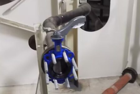
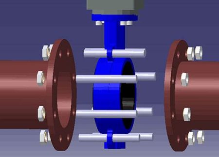
Use four flange bolts first to locate the valve between the flanges and then fixed the flanges together with the pipe by spot welding. Then unloading valve, to weld and seal the flange and pipe fully. Install the valve after the welding area to be completely cooled. So at this point, the valves could gently sandwiched in between two flanges. By this way, the seat sealing would not be damaged.
Check valve after alignment firstly, then the four bolts to be gently clamped . Operate the valve by open and close to check the valve disc flexibility, then stop valve disc in a half open position.
When tightening bolts, it should twist the four bolts in turn. To ensure the normal function of the valve by full open and full closed valve
Note: When installation, make sure the two connection flanges to be parallel to each other, no deformation after welding, and make sure they have the finish sealing surface. When the valve is used for polluting the medium, we recommend that the valve to be installed vertically (the stem level) in the pipeline.
When the valve is used for when the class medium pollution, we suggest that the valve installed vertically (stem) in the pipeline
Operation
Before opration, should check whether the valve installed correctly (installation position, the flange holes), check whether the valve disc and seat sealing ring is suitable for the medium. The valves can be adjusted between 15 °and 70 ° Angle to control the flow of the medium. Please note that don’t run in the valve in the gas corrosive conditions.
Allow the fluid velocity
Liquids: ≤4.5 m/s
Gas:≤20 m/s
Valve should be slowly open and close. To avoid the water hammer in the system.
Disassembly
Remove the valve should be carried out under the condition of the rules (Pipeline shutdown and no pressure).
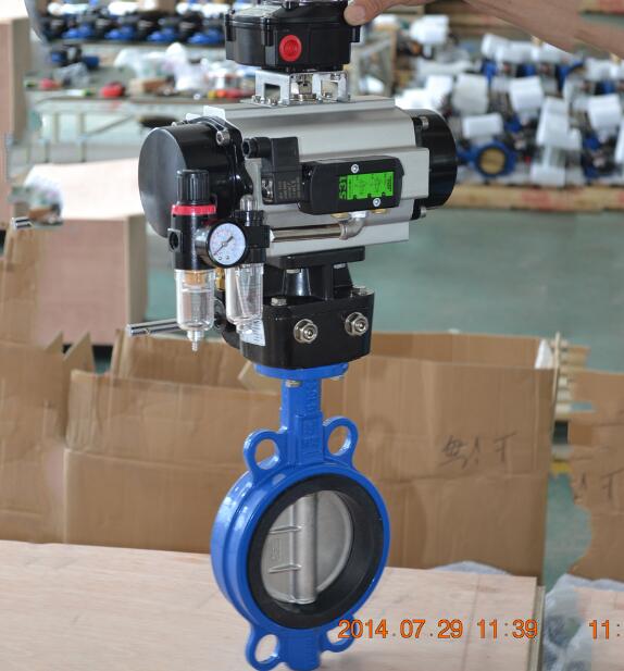
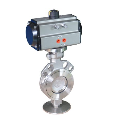
Remove the electric drive or pneumatic device must have a tight security isolation measures.
During the demolition of the valve, valve disc should be placed in the closed position. Slowly and carefully loosen the flange bolts (because the pipe joint may still have pressure).
Remove the valve and put in the right places (such as wooden trough).
Maintenance
This butterfly valve is a maintenance free, please install and use it correctly, Do not need to maintain daily.
Repair
7.1 When repairing, the valve must be properly disassembly. (please refer to the Item 5).
7.2 Please be careful not to damage the valve sealing ring. Remove the valve actuator device (please refer to the electric or pneumatic driving devices remove manual).
7.3 Remove and replace parts.
7.4 After demolition of the top and bottom stem, valve disc can be moved within the seal ring, please pay attention to prevent the disc from falling out.
7.4.1 Loosen the valve stem locating pin.
7.4.2 Remove Stem from the valve body
7.4.3 Loosen the valve plug.
7.4.5 Remove the plug seal, Determine if replacement is required
7.4.6 Removed the stem from the valve, if necessary, can use the threaded rod.
7.4.7 Check the top and bottom stem o-ring gasket, determine whether need to be replaced.
7.4.8 Remove the disc from the seat ring.
7.4.9 Remove the sealing ring from the valve body with the blunt tool.
7.4.10 Check the seat sealing, determine whether need to change.
7.4.11 When installing the seat ring, sprinkle some talcum powder on the contact surface of the sealing ring and body.
7.4.12 insert the locating ring on the seat that connect with the stem into the corresponding groove of the valve body.
7.4.13 To press the sealing ring surface into the valve body, making the valve stem position point to be jointed together tightly with the corresponding groove of the valve body.
7.4.14 Make the whole seal in the valve body.
7.4.15 Check if the location ring of the top and bottom stem seat is correct positioning.( Is it combined with the corresponding grooves in the body of the valve body) Then install the valve disc.
7.4.16 Use the suitable lubricant (such as assembly grease Bernlub Hydrohaf2 etc.),
Lubricate the o-ring gasket of the stem.
7.4.17 Put disc located in the sealing ring.
7.4.18 Insert the lower stem into the body, gently twist on the plug with sealing gasket.
insert upper stem into the body, make the under surface of the square shaft of the upper stem to be parallel with the flange of the valve. Make the groove at the top of the stem shaft parallel to the valve disc.
7.4.19 If the upper stem inserted into the valve body and then pop up, it means there is air in the upper hole of the valve disc. Simply press the valve stem into the hole and maintain, then gently press into a suitable tools (such as blunt screwdriver) carefully inserted between the body and the top of the valve disc, ran out of the compressed air completely, pressed into the valve stem until the square shaft of the upper stem to be parallel with the flange of the valve.
7.4.20 Tighten the valve stem locating pin, fixed valve stem.
7.4.21 Loosen the valve stem locating pin by half circle to check valve stem and valve disc can be turned freely.
7.4.22 Install the driver
7.4.23 When mounting the disc and handle or precision adjusting disc and handle, be sure to align with the valve plate position
Open the valve – counter clockwise
7.6 Close the valve – clockwise
7.7 When installing the repaired valve, please pass the sealing test first