Is the optimal range for butterfly valve loss coefficient K?
Butterfly valves are an essential component in various fluid control systems, serving as a reliable and efficient means of regulating flow. One critical aspect of their performance is the loss coefficient (K), which quantifies the resistance created by the valve during fluid flow. Having an optimal range for the loss coefficient ensures smooth operation, energy efficiency, and reduced costs across industries such as water treatment, chemical processing, and power generation. This article aims to delve into the factors that influence the loss coefficient in butterfly valves and offers insights into determining the optimal range to achieve maximum performance and efficiency.
Introduction
Determining the optimal range for the butterfly valve loss coefficient (K) is a crucial aspect of achieving optimum valve performance, energy efficiency, and cost-effectiveness in fluid control systems. Butterfly valves are widely used across various industries, including water treatment, chemical processing, and power generation, to regulate and control fluid flow effectively. The loss coefficient (K) represents the resistance experienced by the fluid as it passes through the valve, and finding its optimal range can significantly enhance the valve’s overall performance. Several factors influence the loss coefficient, such as valve size, type, flow rate, and fluid properties. Understanding the relationship between these factors and the valve opening angle can help engineers and technicians optimize the loss coefficient for their specific application. Moreover, selecting the appropriate valve size and type, ensuring proper installation and maintenance, and constantly monitoring and adjusting valve performance are essential steps in maintaining the optimal loss coefficient. By focusing on these aspects, industries can experience significant benefits in terms of energy savings, improved performance, and reduced operating costs, ultimately contributing to a more sustainable and efficient fluid control system.
Briefly introduce butterfly valves and their purpose
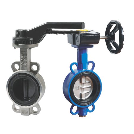
Butterfly valves are a type of quarter-turn valve widely used in various industries for their ability to regulate and control fluid flow effectively. They consist of a disc mounted on a rotating shaft, which, when turned, either allows or restricts the passage of fluid through the valve. The simple yet efficient design of butterfly valves makes them an ideal choice for applications that require quick and precise flow control. Their compact size, ease of maintenance, and cost-effectiveness further contribute to their popularity across industries such as water treatment, chemical processing, power generation, and HVAC systems. By providing a reliable means of controlling fluid flow, butterfly valves play a crucial role in ensuring the smooth operation and efficiency of many industrial processes.
Explain the importance of loss coefficient (K) in valve performance
The loss coefficient (K) is a critical parameter in evaluating valve performance, as it quantifies the resistance or energy loss experienced by the fluid while flowing through the valve. In essence, it represents the relationship between the pressure drop across the valve and the fluid’s kinetic energy. A higher loss coefficient indicates greater energy dissipation and reduced efficiency, which can negatively impact the overall performance of the fluid control system. By optimizing the loss coefficient, engineers and technicians can ensure that the valve operates at its maximum potential, resulting in improved flow control, enhanced energy efficiency, and reduced operating costs. In addition, a well-optimized loss coefficient contributes to the longevity of the valve and other system components by minimizing wear and tear caused by excessive pressure drops or turbulence. Therefore, understanding and managing the loss coefficient is crucial for maintaining optimal valve performance in various industrial applications.
State the objective of the article: to explore the optimal range for butterfly valve loss coefficient (K)
The objective of this article is to delve into the intricacies of determining the optimal range for butterfly valve loss coefficient (K) and its impact on valve performance. By exploring the factors that influence the loss coefficient, such as valve size, type, flow rate, and fluid properties, we aim to provide valuable insights and practical guidance on optimizing this crucial parameter. Through a comprehensive understanding of the relationship between the loss coefficient and valve performance, engineers and technicians can make informed decisions to enhance energy efficiency, reduce operating costs, and improve overall system effectiveness. Ultimately, our goal is to equip readers with the knowledge necessary to optimize the loss coefficient in their respective applications, ensuring the smooth operation and longevity of butterfly valves across various industries.
Background
The background of wafer butterfly valve loss coefficient (K) traces back to the fundamental principles of fluid dynamics and the need for efficient flow control in various industries. The loss coefficient is a dimensionless parameter that quantifies the energy loss or resistance experienced by the fluid as it passes through the valve. This energy loss manifests as a pressure drop, which directly affects the performance and efficiency of the overall system. Over time, researchers and engineers have conducted extensive studies to understand the factors influencing the loss coefficient, such as valve size, type, flow rate, and fluid properties, as well as their interdependence with the valve opening angle. By gaining a comprehensive understanding of these factors and their impact on the loss coefficient, professionals in the field have been able to develop strategies and guidelines for optimizing butterfly valve performance. This optimization has led to significant improvements in energy efficiency, reduced operating costs, and enhanced reliability across a wide range of industrial applications.
Define and explain the concept of loss coefficient (K)
The loss coefficient (K) is a dimensionless parameter that plays a vital role in understanding the performance and efficiency of valves in fluid control systems. It quantifies the resistance or energy loss encountered by a fluid as it flows through a valve, directly impacting the system’s overall effectiveness. This energy loss is expressed as a pressure drop across the valve, which can be calculated using the loss coefficient. The concept of the loss coefficient is rooted in the principles of fluid dynamics, where it serves as a measure of the relationship between the pressure drop and the fluid’s kinetic energy. In essence, a higher loss coefficient indicates a greater degree of energy dissipation and reduced efficiency. By optimizing the loss coefficient, engineers and technicians can ensure that valves operate at their maximum potential, leading to improved flow control, enhanced energy efficiency, and minimized operating costs. Additionally, understanding and managing the loss coefficient contributes to the longevity of the valve and other system components by reducing wear and tear caused by excessive pressure drops or turbulence.
Discuss the factors that affect the loss coefficient in butterfly valves
The loss coefficient in lug butterfly valve is influenced by a multitude of factors, each contributing to the overall performance and efficiency of the valve. One critical factor is the valve design, encompassing aspects such as disc size, shape, and orientation, as well as the valve’s geometric configuration. These design elements can significantly impact the flow patterns, turbulence, and pressure drop experienced by the fluid as it traverses the valve.
Another essential factor is the valve opening angle, which corresponds to the extent of disc rotation from the closed position. As the opening angle varies, so do the flow area and resistance provided by the valve, leading to fluctuations in the loss coefficient.
The nature of the fluid being controlled also plays a crucial role in determining the loss coefficient. Fluid properties, such as density, viscosity, and compressibility, can affect the pressure drop and energy losses encountered by the fluid when flowing through the valve. Additionally, the presence of particles or suspended solids in the fluid can further contribute to pressure losses and increased loss coefficients.
Flow rate is another vital consideration, as higher flow rates can result in augmented turbulence, pressure drop, and energy dissipation within the valve, leading to a higher loss coefficient. In contrast, lower flow rates may yield a lower loss coefficient due to diminished turbulence and pressure losses.
Finally, the installation and piping configuration surrounding the valve can also impact the loss coefficient. Factors like pipe length, bends, and fittings introduce additional resistance and energy losses to the fluid flow, affecting the overall system performance and the valve’s loss coefficient.
Importance of Optimizing Loss Coefficient (K)
The importance of optimizing the loss coefficient (K) in butterfly valves cannot be overstated, as it plays a pivotal role in ensuring the efficiency, performance, and longevity of fluid flow systems across various industries. By minimizing energy losses and pressure drops associated with the valve, system operators can achieve improved flow control, reduced operating costs, and enhanced energy efficiency. Optimizing the loss coefficient is crucial for maintaining the overall effectiveness and reliability of a system, as excessive pressure drops or turbulence can lead to wear and tear on the valve components and the surrounding infrastructure, potentially causing premature failure or costly maintenance requirements. Furthermore, an optimized loss coefficient can contribute to increased process stability and product quality, particularly in sensitive applications where precise flow control is paramount. In industries such as water treatment, chemical processing, and oil and gas, optimizing the loss coefficient can directly impact the safety and environmental footprint of operations, underscoring the significance of this parameter in both economic and sustainability contexts. Ultimately, the optimization of the loss coefficient in butterfly valves serves as a testament to the ongoing pursuit of engineering excellence, fostering innovations and advancements in valve design and technology that continue to drive the evolution of fluid control systems worldwide.
Explain how optimizing the loss coefficient can improve valve performance
Optimizing the loss coefficient in electric butterfly valve is a crucial aspect of enhancing valve performance and overall system efficiency. By minimizing energy losses and pressure drops associated with the valve, engineers can achieve more precise and effective flow control. An optimized loss coefficient leads to reduced turbulence and smoother fluid flow, which in turn minimizes wear and tear on valve components and surrounding infrastructure, prolonging their service life and reducing maintenance costs. Furthermore, an optimized loss coefficient contributes to increased process stability and responsiveness, which is particularly important in sensitive applications where accurate flow control is essential for maintaining product quality and operational safety. In summary, optimizing the loss coefficient directly impacts valve performance by promoting efficient fluid flow, extending component lifespan, and ensuring greater process control, ultimately contributing to the overall effectiveness and reliability of fluid control systems across various industries.
Discuss the impact on energy efficiency and operating costs
The optimization of the loss coefficient in flanged butterfly valve has a significant impact on energy efficiency and operating costs within fluid control systems. By minimizing pressure drops and energy losses associated with the valve, the system can operate more efficiently, leading to reduced energy consumption and lower operational expenses. An optimized loss coefficient ensures that the fluid flows smoothly with minimal turbulence, which not only contributes to enhanced energy efficiency but also reduces wear and tear on valve components and surrounding infrastructure. As a result, maintenance costs and downtime are diminished, further contributing to the overall cost-effectiveness of the system. Furthermore, improved energy efficiency can translate into a more environmentally friendly operation, as less energy is wasted during the fluid flow process. In conclusion, optimizing the loss coefficient in butterfly valves directly impacts both energy efficiency and operating costs, promoting a more sustainable and cost-effective fluid control system across various industries and applications.
Highlight the significance in various industries, such as water treatment, chemical processing, and power generation
The optimization of the loss coefficient in butterfly valves holds substantial significance across various industries, including water treatment, chemical processing, and power generation. In the water treatment industry, efficient fluid flow control is vital for maintaining water quality and ensuring the proper functioning of purification processes. An optimized loss coefficient contributes to precise flow regulation, enabling accurate dosing of treatment chemicals and minimizing energy consumption. In chemical processing, where reactions and separation processes often require exact control of fluid flow rates and pressures, an optimized loss coefficient is crucial for achieving optimal process conditions, ensuring product quality, and maintaining safety standards. Similarly, the power generation industry relies heavily on efficient fluid control systems for cooling, steam generation, and other critical processes. Reducing energy losses and pressure drops through the optimization of the loss coefficient can lead to improved system efficiency, lower operating costs, and enhanced reliability of power generation equipment. In summary, the importance of optimizing the loss coefficient in butterfly valves transcends multiple industries, playing a pivotal role in maintaining operational efficiency, product quality, and environmental sustainability.
Determining the Optimal Range for Loss Coefficient (K)
Determining the optimal range for the loss coefficient (K) in butterfly valves is a critical aspect of ensuring efficient fluid flow control, system performance, and long-term reliability across various industries and applications. Establishing the ideal range for the loss coefficient involves taking into account several factors such as valve design, fluid properties, flow rate, and the specific requirements of the application. A comprehensive understanding of these factors, along with an in-depth analysis of the valve’s performance characteristics, allows engineers to identify the optimal range that strikes a balance between minimizing energy losses and pressure drops while maintaining precise flow control.
In the context of valve design, engineers must consider elements such as disc size, shape, orientation, and overall valve geometry to achieve an optimal loss coefficient. These design features can significantly impact fluid flow patterns, turbulence, and pressure drop experienced by the fluid as it traverses the valve. Moreover, the valve opening angle, which corresponds to the extent of disc rotation from the closed position, plays a crucial role in determining the optimal loss coefficient range, as it directly affects the flow area and resistance provided by the valve.
Fluid properties, such as density, viscosity, and compressibility, also influence the optimal range for the loss coefficient. Engineers must take into account the unique characteristics of the fluid being controlled to ensure that the valve operates efficiently and effectively under the given conditions.
Flow rate is another essential factor to consider when determining the optimal loss coefficient range. Higher flow rates can result in increased turbulence, pressure drop, and energy dissipation within the valve, impacting the loss coefficient and overall system performance. Conversely, lower flow rates may yield a lower loss coefficient due to reduced turbulence and pressure losses.
Finally, the specific requirements of the application play a vital role in establishing the optimal range for the loss coefficient. Industries such as water treatment, chemical processing, and power generation each have distinct operational needs and constraints, necessitating tailored approaches to optimizing the loss coefficient in butterfly valves to ensure optimal performance, efficiency, and reliability. By considering these factors and conducting thorough performance analyses, engineers can determine the optimal range for the loss coefficient, ultimately contributing to improved fluid control systems across a wide array of applications.
Discuss the relationship between valve opening angle and loss coefficient
The relationship between the valve opening angle and the loss coefficient in butterfly valves plays a critical role in determining the overall efficiency and performance of fluid control systems. The valve opening angle refers to the extent of disc rotation from the closed position, which directly impacts the flow area and resistance provided by the valve. As the opening angle increases, the flow area enlarges, allowing more fluid to pass through the valve with reduced resistance. Consequently, the loss coefficient, which represents the energy losses and pressure drops associated with the valve, tends to decrease as the opening angle widens.
Conversely, as the valve opening angle narrows, the flow area diminishes, resulting in increased resistance and higher energy losses due to the restricted passage of the fluid. This leads to an elevated loss coefficient, indicating greater pressure drops and reduced efficiency within the fluid control system. Therefore, understanding the relationship between the valve opening angle and the loss coefficient is essential for engineers when designing and selecting butterfly valves, as it enables them to strike a balance between efficient flow control and minimal energy losses, ultimately enhancing the performance and reliability of the system across various applications and industries.
Present data and research studies on the optimal range for different types of butterfly valves
While specific data and research studies on the optimal range for different types of electric butterfly valve may vary, a general understanding of their performance characteristics can be derived from the existing body of knowledge. Researchers and engineers have conducted numerous studies to analyze and compare the performance of various butterfly valve designs, such as concentric, double-offset, and triple-offset valves, with the goal of identifying the optimal loss coefficient range for each type.
These studies often involve experimental testing and computational fluid dynamics (CFD) simulations, which provide valuable insights into the fluid flow patterns, pressure drops, and energy losses associated with each valve design under varying operating conditions. By analyzing this data, engineers can identify the optimal range for the loss coefficient that ensures efficient flow control, minimal energy losses, and reduced wear and tear on the valve components.
For instance, research has shown that triple-offset butterfly valves generally exhibit a lower loss coefficient compared to concentric and double-offset designs, due to their unique geometry and sealing mechanism that reduces turbulence and pressure drop within the valve. This makes them particularly suitable for applications requiring high-performance flow control and low-pressure losses.
In conclusion, while specific data and research studies on the optimal range for different types of butterfly valves may vary, the collective knowledge gained from these efforts has significantly contributed to the ongoing development and optimization of butterfly valve technology. This, in turn, enables engineers to design and select the most appropriate valve type for a given application, ensuring optimal system performance and reliability across a wide array of industries and fluid control scenarios.
Explain how to determine the optimal range for a specific application by considering factors such as flow rate, pressure drop, and fluid properties
Determining the optimal range for the loss coefficient in butterfly valves for a specific application requires a thorough understanding of various factors, such as flow rate, pressure drop, and fluid properties. By carefully considering these factors, engineers can tailor the valve selection and design to achieve maximum efficiency and performance in the given context.
Flow rate is a crucial factor to consider, as it directly impacts the loss coefficient and overall system performance. Higher flow rates can result in increased turbulence, pressure drop, and energy dissipation within the valve, while lower flow rates may yield a lower loss coefficient due to reduced turbulence and pressure losses. Engineers must evaluate the desired flow rate for the application and choose a valve design that provides optimal flow control within that range, minimizing energy losses and pressure drops.
Pressure drop is another essential aspect to consider when determining the optimal range for the loss coefficient. In many applications, it is necessary to maintain a specific pressure differential across the valve to ensure proper fluid flow and system performance. Engineers must analyze the relationship between the valve opening angle and pressure drop to identify the optimal range that meets the required pressure differential while minimizing energy losses.
Fluid properties, such as density, viscosity, and compressibility, also play a significant role in determining the optimal loss coefficient range. Different fluids exhibit unique characteristics that can influence the valve’s performance and energy losses. Engineers must account for these fluid properties when selecting and designing the butterfly valve to ensure efficient operation under the given conditions.
In conclusion, determining the optimal range for the loss coefficient in butterfly valves for a specific application involves a careful analysis of factors such as flow rate, pressure drop, and fluid properties. By considering these aspects and conducting thorough performance evaluations, engineers can select and design the most suitable valve type for the application, ensuring optimal efficiency, performance, and reliability within the fluid control system.
Practical Tips for Optimizing Butterfly Valve Loss Coefficient (K)
Optimizing the loss coefficient (K) of butterfly valves is essential for enhancing fluid control system efficiency and performance across various industries and applications. To achieve this optimization, several practical tips can be employed by engineers and technicians during the design, selection, and maintenance of butterfly valves.
Firstly, it’s crucial to choose the appropriate butterfly valve type based on the specific application requirements. Concentric, double-offset, and triple-offset butterfly valves each exhibit unique performance characteristics that may be more suitable for certain scenarios. For instance, triple-offset valves are known for their lower loss coefficient and improved sealing capabilities, making them ideal for high-performance applications with stringent pressure drop and leakage requirements.
Secondly, optimizing the valve design by considering factors such as disc size, shape, and orientation can significantly impact the fluid flow patterns, turbulence, and pressure drop experienced by the fluid as it passes through the valve. Engineers should conduct thorough computational fluid dynamics (CFD) simulations and experimental testing to fine-tune these design elements, ensuring minimal energy losses and pressure drops while maintaining precise flow control.
Another practical tip is to carefully evaluate the relationship between the valve opening angle and the loss coefficient. By understanding how the fluid flow area and resistance change as the opening angle varies, engineers can identify the optimal range that balances efficient flow control with minimal energy losses.
Moreover, accounting for the fluid properties, such as density, viscosity, and compressibility, is vital when selecting and designing the butterfly valve. Different fluids can influence the valve’s performance and energy losses in distinct ways, so it’s essential to ensure that the chosen valve operates efficiently under the given fluid conditions.
Regular maintenance and inspection of butterfly valves also play a significant role in optimizing the loss coefficient. Proper upkeep helps to prevent wear and tear on valve components, which can lead to increased energy losses and reduced system performance over time. By conducting routine checks and addressing any issues promptly, technicians can ensure that the butterfly valve maintains its optimal loss coefficient and continues to perform efficiently throughout its service life.
In conclusion, optimizing the butterfly valve loss coefficient (K) can be achieved by following practical tips such as selecting the appropriate valve type, fine-tuning the valve design, understanding the relationship between the valve opening angle and loss coefficient, accounting for fluid properties, and performing regular maintenance. By employing these strategies, engineers and technicians can enhance the efficiency and performance of fluid control systems across a wide range of applications and industries.
Provide guidance on selecting the appropriate valve size and type
Selecting the appropriate valve size and type is a critical aspect of designing and implementing efficient fluid control systems across various industries and applications. To make an informed decision, engineers must consider factors such as application requirements, fluid properties, flow rate, pressure drop, and system compatibility. By evaluating these aspects, the most suitable valve size and type can be chosen to ensure optimal performance, reliability, and longevity of the fluid control system.
Application requirements play a significant role in determining the ideal valve size and type. Factors such as required flow control precision, allowable leakage rates, and operating temperature and pressure ranges must be taken into account. For example, triple-offset butterfly valves may be preferred for high-performance applications with stringent leakage and pressure drop requirements, while concentric or double-offset valves might be more suitable for less demanding scenarios.
Fluid properties, including density, viscosity, and compressibility, also influence the selection process. Engineers should choose a valve size and type that can efficiently handle the unique characteristics of the fluid being controlled, ensuring minimal energy losses and pressure drops during operation.
Flow rate and pressure drop requirements are essential considerations when selecting the appropriate valve size. The chosen valve should be capable of providing precise flow control within the desired range while maintaining an acceptable pressure differential across the valve to ensure proper system performance.
System compatibility is another critical factor to consider. The selected valve size and type should be compatible with the existing piping, fittings, and other components of the fluid control system. This ensures seamless integration, minimizes potential issues during installation, and reduces the likelihood of system disruptions during operation.
In conclusion, providing guidance on selecting the appropriate valve size and type involves a thorough evaluation of application requirements, fluid properties, flow rate, pressure drop, and system compatibility. By considering these factors and conducting careful analysis, engineers can make informed decisions that contribute to the overall efficiency, performance, and reliability of fluid control systems across various industries and applications.
Discuss the importance of proper installation and maintenance
Proper installation and maintenance of fluid control systems, including butterfly valves, are of paramount importance to ensure optimal performance, efficiency, and longevity across various industries and applications. The installation process directly impacts the functionality and reliability of the system by ensuring that each component is correctly positioned, aligned, and integrated with the existing infrastructure. A well-executed installation can prevent issues such as leaks, pressure drops, and premature wear and tear on valve components, which may arise from misaligned or improperly fitted parts.
Maintenance, on the other hand, plays a crucial role in preserving the optimal functioning of the system over time. Regular inspections, cleaning, and component replacement as needed can help identify and address potential problems before they escalate into more significant issues that may compromise the system’s efficiency or lead to costly downtime. By conducting routine maintenance checks, technicians can ensure that each element of the fluid control system, including the butterfly valves, continues to operate at peak efficiency and within the desired performance parameters throughout its service life.
In conclusion, the importance of proper installation and maintenance cannot be overstated when it comes to fluid control systems and butterfly valves. These practices not only guarantee optimal system performance and efficiency but also contribute to the extended service life and reduced operational costs of the system. By emphasizing the significance of proper installation and maintenance, engineers and technicians can help ensure the overall success and reliability of fluid control systems across various industries and applications.
Recommend strategies for monitoring and adjusting valve performance to maintain the optimal loss coefficient
Monitoring and adjusting valve performance to maintain the optimal loss coefficient is essential for ensuring the efficiency, reliability, and overall success of fluid control systems. Several strategies can be employed by engineers and technicians to achieve this objective.
Firstly, implementing a regular monitoring schedule using advanced sensors, data acquisition systems, and performance analysis tools can provide valuable insights into the real-time operation of the butterfly valves. By tracking parameters such as flow rate, pressure drop, and valve opening angle, engineers can identify potential deviations from the optimal loss coefficient range and make necessary adjustments to restore efficient performance.
Secondly, conducting periodic performance assessments through computational fluid dynamics (CFD) simulations and experimental testing can help evaluate the relationship between the valve opening angle and the loss coefficient under varying operating conditions. These evaluations enable engineers to fine-tune the valve design and make informed decisions about the appropriate opening angle range to optimize flow control and minimize energy losses.
Another recommended strategy is to invest in adaptive control systems and automated actuators that can intelligently adjust valve performance in response to changes in system conditions, such as fluctuating flow rates or pressure differentials. These advanced technologies can maintain the optimal loss coefficient by continuously monitoring and adjusting the valve opening angle to balance efficient flow control with minimal energy losses.
Lastly, don’t underestimate the importance of proper maintenance and timely component replacements. Ensuring that the valve components are in good working condition and free from wear and tear can significantly impact the valve’s performance and its ability to maintain the optimal loss coefficient. Regular inspections, cleaning, and maintenance can help technicians identify and address potential issues before they escalate, ensuring that the butterfly valve continues to operate efficiently throughout its service life.
In conclusion, adopting strategies such as regular monitoring, performance assessments, adaptive control systems, and proper maintenance can significantly contribute to monitoring and adjusting valve performance to maintain the optimal loss coefficient. By following these recommendations, engineers and technicians can ensure the long-term efficiency, reliability, and success of fluid control systems across various industries and applications.
Case Studies
Case studies in the field of fluid control systems, particularly those involving butterfly valves, provide valuable insights into the real-world challenges, solutions, and successes experienced by engineers and technicians across various industries and applications. These case studies often highlight the importance of selecting the appropriate valve type and size, optimizing design parameters, and implementing proper installation and maintenance practices to achieve optimal system performance, efficiency, and reliability.
For instance, a case study focusing on the water treatment industry may demonstrate how the implementation of triple-offset butterfly valves contributed to improved flow control and reduced leakage rates in a high-pressure pumping station. The study could detail the process of selecting the ideal valve type, conducting thorough performance evaluations, and fine-tuning the valve design to ensure efficient operation under the specific application requirements and fluid conditions. In doing so, the case study would showcase the tangible benefits of applying the principles of optimal loss coefficient management and valve selection in a real-world scenario.
Another case study might explore the challenges faced by engineers in the oil and gas industry, where extreme operating conditions and stringent safety standards necessitate the use of highly reliable and efficient fluid control systems. By examining the successful integration of double-offset butterfly valves in a complex pipeline network, the case study could reveal the importance of proper valve sizing, design optimization, and compatibility with existing infrastructure to minimize pressure drops, energy losses, and potential risks associated with system failures.
Additionally, case studies in the field of HVAC (heating, ventilation, and air conditioning) can offer valuable insights into the role of butterfly valves in maintaining optimal temperature and pressure conditions within large-scale commercial and industrial buildings. By analyzing the successful implementation of concentric butterfly valves in an HVAC system, the case study could emphasize the importance of proper valve selection, installation, and maintenance to ensure efficient air distribution, energy savings, and overall system performance.
In conclusion, case studies involving butterfly valves and fluid control systems serve as invaluable resources for engineers and technicians seeking to learn from real-world experiences and apply these lessons to their own projects. By examining the successes and challenges faced by professionals across various industries and applications, case studies contribute to the ongoing development and optimization of butterfly valve technology, ultimately enhancing the efficiency, performance, and reliability of fluid control systems worldwide.
Share real-world examples of successful butterfly valve optimization projects
Successful butterfly valve optimization projects in real-world scenarios demonstrate the practical application of engineering principles and showcase the tangible benefits of efficient fluid control systems. For example, a large-scale chemical processing plant might have faced challenges with pressure drops and leakage rates in their existing fluid control system. By replacing the conventional gate valves with triple-offset butterfly valves, the plant was able to significantly reduce pressure drops, improve flow control precision, and minimize leakage rates, resulting in increased efficiency and cost savings. Another example could be a municipal water treatment facility that needed to upgrade its aging infrastructure to meet growing demand and stricter environmental regulations. By implementing double-offset butterfly valves with advanced actuation and control systems, the facility successfully optimized flow control, minimized energy losses, and enhanced overall system performance while complying with regulatory requirements. These real-world examples highlight the importance of proper butterfly valve selection, design optimization, and maintenance practices in achieving optimal performance and efficiency across various industries and applications.
Highlight the benefits achieved in terms of energy savings, improved performance, and reduced operating costs
The successful optimization of butterfly valves in fluid control systems can lead to numerous benefits, including energy savings, improved performance, and reduced operating costs. By selecting the appropriate valve type, size, and design for specific applications, engineers can minimize pressure drops and turbulence, resulting in more efficient fluid flow and lower energy consumption. This energy efficiency directly translates into cost savings, as less energy is required to maintain desired flow rates and system performance. Improved valve performance also contributes to enhanced process control, ensuring that fluid flow rates and pressures are maintained within desired ranges. This precise control enables smoother operation and fewer fluctuations, ultimately leading to increased productivity and reduced downtime. Moreover, optimized butterfly valves with proper maintenance practices can extend the service life of the valves and other system components, lowering the frequency of replacements and repairs. This longevity results in reduced operating costs over time, further emphasizing the value of investing in butterfly valve optimization for various industries and applications.
Conclusion
In fluid control systems, the loss coefficient (K) is a crucial parameter that quantifies the pressure drop across a valve due to flow resistance. The optimal range for the butterfly valve loss coefficient is critical for ensuring efficient operation, reduced energy consumption, and minimal pressure losses. By striving to achieve and maintain the ideal K value, engineers can significantly enhance the performance, reliability, and longevity of fluid control systems across various industries and applications.
There are several factors that contribute to determining the optimal range for butterfly valve loss coefficient K, including valve type, size, design, and operating conditions. Proper selection of valve type and size, as well as optimizing design parameters, such as the valve opening angle and disc shape, are essential steps in achieving the desired K value. Engineers must also consider fluid properties, flow rate, and system compatibility when selecting and designing butterfly valves to ensure that the optimal loss coefficient is maintained under varying conditions.
To monitor and adjust valve performance for maintaining the optimal K value, engineers can employ strategies such as regular monitoring using advanced sensors and data acquisition systems, periodic performance assessments through computational fluid dynamics (CFD) simulations and experimental testing, and implementing adaptive control systems with automated actuators. Additionally, proper maintenance practices and timely component replacements are crucial in preserving the valve’s ability to maintain the optimal loss coefficient throughout its service life.
Real-world examples of successful butterfly valve optimization projects highlight the tangible benefits of achieving the optimal range for the loss coefficient K. These benefits include energy savings, improved performance, and reduced operating costs, all of which contribute to the overall efficiency and success of fluid control systems. By learning from these examples and applying the principles of optimal loss coefficient management, engineers can continue to advance the field of fluid control and develop innovative solutions that meet the ever-evolving demands of various industries and applications.
In conclusion, understanding the importance of the optimal range for butterfly valve loss coefficient K and striving to achieve it through appropriate valve selection, design optimization, and performance monitoring are vital for the success of fluid control systems. By focusing on these aspects, engineers and technicians can ensure that butterfly valves operate at peak efficiency, ultimately contributing to the efficient, reliable, and cost-effective management of fluid flow across a wide range of applications and industries.
Recap the importance of determining the optimal range for butterfly valve loss coefficient (K)
In conclusion, determining the optimal range for butterfly valve loss coefficient (K) is of paramount importance in fluid control systems to ensure efficient operation, reduced energy consumption, and minimal pressure losses. The optimal K value directly impacts the performance, reliability, and longevity of fluid control systems across various industries and applications. By carefully selecting the appropriate valve type, size, design, and considering operating conditions, engineers can achieve and maintain the desired K value for efficient fluid flow control. Furthermore, employing strategies such as regular monitoring, performance assessments, adaptive control systems, and proper maintenance practices can help preserve the valve’s ability to maintain the optimal loss coefficient throughout its service life. In essence, understanding and focusing on the optimal range for butterfly valve loss coefficient (K) plays a crucial role in enhancing the overall efficiency and success of fluid control systems.
Emphasize the potential benefits of optimizing valve performance
Optimizing valve performance in fluid control systems offers a multitude of potential benefits that can significantly impact the efficiency, reliability, and cost-effectiveness of various industries and applications. By achieving optimal valve performance, engineers can minimize pressure drops and turbulence, resulting in more efficient fluid flow and lower energy consumption. This directly translates into substantial energy savings and reduced operating costs. Additionally, optimized valve performance enhances process control, ensuring precise maintenance of fluid flow rates and pressures, which in turn leads to smoother operation, increased productivity, and reduced downtime. Furthermore, proper valve selection, design optimization, and maintenance practices can extend the service life of valves and other system components, lowering the frequency of replacements and repairs. In summary, optimizing valve performance presents a wide range of benefits that contribute to the overall success and sustainability of fluid control systems across numerous industries.
Encourage readers to apply the information provided to their own applications and industries
We encourage readers to apply the valuable information provided in this article to their own applications and industries, as optimizing valve performance and understanding the importance of parameters like the butterfly valve loss coefficient (K) can lead to substantial benefits across various fluid control systems. By leveraging the insights shared here, you can make informed decisions regarding valve selection, design optimization, and maintenance practices that ultimately contribute to more efficient, reliable, and cost-effective fluid control solutions. Remember, every industry and application presents unique challenges and requirements; therefore, adapting these principles to your specific needs and context is crucial for achieving optimal results. By doing so, you will not only enhance the performance and longevity of your fluid control systems but also contribute to the ongoing development and innovation within your industry.


-370x270.jpg)