Unlock the Secrets of Flow Rate Calculations with Butterfly Valve Cv
In the world of fluid dynamics, understanding flow rate calculations is crucial. It’s a concept that plays a pivotal role in various industries, from oil and gas to wastewater management. One key player in managing and controlling this flow rate is the butterfly valve. This humble yet vital component is often overlooked, but its role is paramount in ensuring the smooth operation of many systems. This blog post aims to demystify the process of calculating flow rates through butterfly valve, shedding light on its importance, how it works, and offering practical tips for accurate calculations. So, whether you’re a seasoned engineer or a curious novice, let’s delve into the fascinating world of flow rate calculations through butterfly valve.
Introduction
Butterfly valves are an essential component in various industrial applications, playing a critical role in managing and regulating the flow rate of fluids within pipelines. The butterfly valve, named for the wing-like action of the disc, operates by rotating a disc to either allow fluid to pass through or to block it completely. The control it provides over the fluid flow is integral to the efficient operation of many systems, from water treatment plants to petroleum refineries. However, the process of calculating flow rates through these butterfly valves can often seem like a complex task shrouded in mystery. To demystify this process, it’s important to understand that the flow rate through a butterfly valve is influenced by factors such as the size of the valve, the pressure differential across the valve, the position of the valve disc (i.e., how far it is opened or closed), and the properties of the fluid flowing through it. By accurately measuring these variables and applying them to established flow equations, one can effectively calculate the flow rate through a butterfly valve. These calculations are crucial in designing and operating efficient systems, allowing operators to accurately predict and control the flow of fluid, thereby ensuring the system works at its optimum capacity. Understanding the process of flow rate calculation through butterfly valves is therefore not just a theoretical exercise, but a practical necessity for professionals in many industries.
Brief explanation about flow rate calculations.
Flow rate calculations are a fundamental concept in fluid dynamics, used to quantify the volume of fluid that passes through a given cross-sectional area per unit of time. This measurement is commonly expressed in units such as gallons per minute (GPM), liters per second (L/s), or cubic meters per hour (m³/h), depending on the context and industry. Flow rate can be calculated using various methods, but the most common involves measuring the velocity of the fluid and the cross-sectional area of the pipe or conduit it’s moving through. The basic formula for this is Q=AV, where Q represents the flow rate, A is the cross-sectional area, and V is the velocity of the fluid. Understanding how to calculate flow rate is essential in many fields, from engineering and physics to environmental science and medicine, as it allows professionals to design, control, and optimize fluid transport systems efficiently.
Importance of understanding flow rate calculations in fluid dynamics.
Understanding flow rate calculations is of utmost importance in the field of fluid dynamics, a branch of physics that deals with the study of fluids in motion. Flow rates dictate crucial aspects of how fluid systems are designed and operated. For instance, in the design phase of a pipeline or a hydraulic system, knowing the flow rate is essential to determine the suitable size of pipes, the type of pump needed, and the appropriate valve selection. In the operational phase, understanding flow rate calculations can help diagnose issues, optimize performance, and prevent potential failures. By accurately predicting and controlling flow rates, engineers can ensure the efficient and safe operation of systems, whether it’s water flowing through a city’s pipe network, oil flowing through a refinery, or blood flowing through a medical device. Furthermore, in environmental sciences, understanding flow rates is key to managing and protecting our water resources. Therefore, mastering flow rate calculations is a fundamental skill for anyone working with fluid systems.
Introduction to butterfly valve and their role in controlling flow rate.
Butterfly valves are a type of flow control device widely used in various industrial applications. Named for the butterfly-like disc that rotates within the valve body, these valves offer a simple and effective way to regulate the flow of fluids through piping systems. The disc, which is mounted on a rotating shaft, can be turned to any angle, allowing for precise control over the flow rate. When the disc is aligned with the direction of flow (i.e., parallel), the valve is fully open, allowing maximum flow. Conversely, when the disc is perpendicular to the flow, the valve is fully closed, halting fluid flow entirely. By adjusting the disc’s position between these two extremes, operators can achieve any desired flow rate within the valve’s capacity. This ability to finely adjust flow rates makes butterfly valves an indispensable tool in many industries, including water and wastewater treatment, oil and gas production, and chemical processing. Understanding the operation and control of butterfly valves is therefore key to managing flow rates effectively in these and other fluid handling systems.
Understanding Butterfly Valve
Butterfly valves are an integral part of many industrial and commercial processes that involve the flow of liquids or gases. They are a type of quarter-turn valve, which means they open or close with a 90-degree turn of the handle. The central feature of the butterfly valve is its disc, shaped like a butterfly’s wings, mounted on a rotating shaft. When the handle is turned, the disc rotates around the shaft, either parallel or perpendicular to the flow, creating a passage for the fluid to flow through or blocking it off entirely.
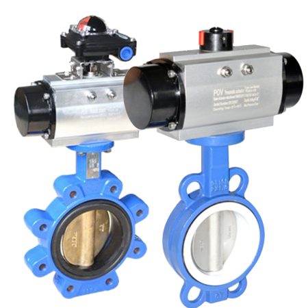
The simplicity of their design makes wafer butterfly valve highly versatile and efficient. They are lightweight, easy to install, and require minimal maintenance compared to other types of valves. Moreover, they provide quick and easy control over fluid flow, making them ideal for applications where flow needs to be adjusted frequently or rapidly shut off.
Butterfly valves can be used in a wide range of applications, from water distribution in municipal utilities to flow control in chemical processing plants, oil and gas pipelines, HVAC systems, and even fire protection systems. They can handle a broad range of temperatures and pressures, and with appropriate material selection, they can be used with corrosive or abrasive fluids.
However, it’s important to note that while butterfly valves are excellent for controlling flow, they may not provide a perfect seal when closed, especially in high-pressure applications. Therefore, they are often not recommended for situations where a zero-leakage seal is required.
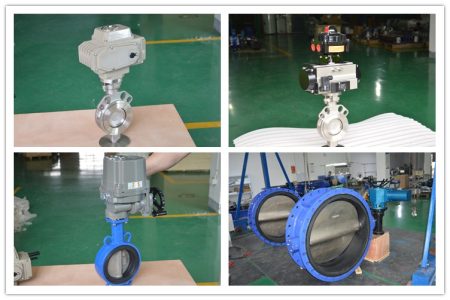
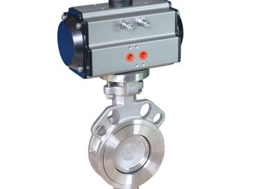
In terms of operation, butterfly valves can be operated manually, or they can be automated using electric, pneumatic, or hydraulic actuators. Automated butterfly valves offer the advantage of remote control and can be programmed to respond to changes in system conditions, enhancing the overall efficiency and safety of the process.
In conclusion, understanding butterfly valves – their design, operation, advantages, and limitations – is crucial for anyone involved in the design or operation of fluid handling systems. Their ability to control flow rates effectively and efficiently makes them an invaluable tool in a wide variety of industrial and commercial applications.
Detailed description of butterfly valve.
Butterfly valves are a unique type of quarter-turn valve that are used in various industrial applications for regulating fluid flow. They derive their name from the disc inside the valve body, which is similar to a butterfly’s wings. This disc is attached to a shaft that rotates when the handle or actuator of the valve is turned. When the disc is rotated to align with the flow direction, the valve is in its fully open state, allowing fluid to pass through unhindered. Conversely, when the disc is rotated to be perpendicular to the flow, the valve is in its fully closed state, blocking all fluid flow.
The design of butterfly valves is simple yet efficient. They are typically compact and lightweight, making them easy to install and maintain. They also offer fast operation, as they only require a 90-degree turn to go from a fully open to fully closed position. This makes them particularly useful in applications where quick shut-off is required.
Butterfly valves are versatile and can be used with a wide range of fluids and gases at varying temperatures and pressures. They are commonly found in water distribution systems, chemical processing plants, and oil and gas pipelines, among other settings. The materials used for the disc and the sealing mechanism can be selected based on the specific application to ensure optimal performance and longevity.
One key aspect to note about butterfly valves is that they may not provide a completely leak-proof seal when closed. This is due to the design of the disc that, even in the closed position, does not completely isolate the two sides of the valve. Therefore, they may not be suitable for applications where zero leakage is essential.
In terms of operation, butterfly valves can be manually operated or automated. Automated valves use electric, pneumatic, or hydraulic actuators and can be controlled remotely or programmed to respond to certain system conditions.
Overall, understanding the detailed workings of butterfly valves is crucial for those involved in industries where fluid flow control is paramount. Their efficient design and operational versatility make them a popular choice in numerous applications.
Working principle of butterfly valve.
The working principle of butterfly valves is based on a simple but effective mechanism. Essentially, they consist of a disc, which is fastened to a rotating shaft. As the name suggests, this disc is shaped like a butterfly’s wings, hence the valve’s name. When the valve is open, the disc is turned so that it allows fluid or gas to pass through, aligning itself with the direction of the flow. However, when the valve is closed, the disc is rotated by 90 degrees, effectively blocking the passage and preventing any flow. The operation of the valve, whether opening or closing, is accomplished by turning the valve’s handle or actuator, which in turn rotates the shaft and the attached disc. This simple quarter-turn mechanism allows for quick and efficient control of flow, making butterfly valves an essential component in many industrial systems where regulation of fluid or gas flow is required.
Various applications of butterfly valve in different industries.
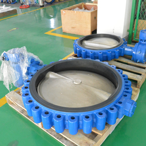
Butterfly valves are widely used across several industries due to their efficiency and versatility. In the water and wastewater industry, they are commonly used for their ability to handle large flow volumes efficiently, making them ideal for use in water distribution systems and sewage treatment plants. In the oil and gas industry, butterfly valves are used in pipelines for isolating and regulating the flow of crude oil and natural gas. They are also used in refining processes due to their ability to handle high temperatures and pressures. In the chemical industry, butterfly valves are often preferred for handling corrosive and aggressive chemicals thanks to their robust design and the availability of corrosion-resistant materials. They are also found in food and beverage industries where they are used to control the flow of liquid food products, such as milk or beer, with the added advantage of being easy to clean and maintain. In HVAC systems, butterfly valves are used to control the flow of hot and cold air. Furthermore, in power generation plants, they are used in cooling water systems, feed water systems, and scrubbing systems. This wide range of applications showcases the adaptability and utility of butterfly valves in different industrial settings.
Role of Butterfly Valve in Flow Rate Control
Butterfly valves play a pivotal role in flow rate control across various industries. Their design and operational mechanism make them ideal for controlling the rate of fluid or gas passing through a system. As the name suggests, a butterfly valve has a disc mounted on a rotating shaft, much like the wings of a butterfly. The position of this disc determines the flow rate of the medium. When the disc is aligned parallel to the flow direction, the valve is fully open, offering minimal resistance and allowing maximum flow. Conversely, when the disc is rotated to a position perpendicular to the flow, it blocks the passage completely, stopping the flow. However, the true effectiveness of butterfly valves lies in their ability to achieve intermediate positions. The operator can rotate the disc to any angle between the fully open and fully closed positions, providing fine control over the flow rate. This is particularly useful in industries where precise flow regulation is necessary, such as in chemical processing plants or food and beverage production facilities. The simplicity of operation, combined with durability and low maintenance requirements, makes butterfly valves an efficient solution for flow rate control. They offer a reliable way to regulate flow rates, contributing significantly to process optimization and efficiency in many industrial applications.
Explanation of how butterfly valve control the flow of fluids.
Butterfly valves control the flow of fluids using a simple but effective mechanism. The valve features a circular disc attached to a rotating shaft. When the valve is in the open position, the disc is turned parallel to the direction of fluid flow, allowing the fluid to pass through freely with minimal resistance. As the valve is closed, the disc is rotated by 90 degrees until it is perpendicular to the flow direction, thereby blocking the passage and halting the fluid flow. This operation is typically achieved through a manual handle or an actuator, which controls the rotation of the shaft and, subsequently, the position of the disc. What sets butterfly valves apart is their ability to control the flow rate. By adjusting the angle of the disc, operators can accurately regulate the amount of fluid that passes through the valve, allowing for precise flow control. This makes butterfly valves extremely versatile and widely used in many industries, from water distribution and waste treatment to oil and gas, chemical processing, and more.
Discussing the relationship between the position of the butterfly valve and the flow rate.
The position of the butterfly valve and the flow rate share a direct relationship. The butterfly valve operates using a disc that is attached to a rotating shaft. The rotation of this shaft either opens or closes the valve, thus controlling the flow rate of the fluid passing through it. When the disc is parallel to the flow of the fluid—the fully open position—the flow rate is at its maximum as there is minimal resistance to the fluid’s passage. However, when the disc is rotated 90 degrees to a position perpendicular to the flow—the fully closed position—the flow rate drops to zero as the passage is completely blocked. In between these extremes, adjusting the angle of the disc allows for fine control of the flow rate. For instance, if the disc is positioned at a 45-degree angle, the valve is half-open, and the flow rate will be approximately half of the maximum possible. Hence, by manipulating the position of the butterfly valve, operators can precisely control the flow rate to meet specific requirements.
Real-life examples of flow rate control using butterfly valve.
Butterfly valves find numerous applications in real-world scenarios where flow rate control is crucial. For example, in activated sludge plants, accurate airflow control is achieved by utilizing butterfly valves, providing a cost-effective alternative to more expensive linear valves. Similarly, advances in butterfly valve technology have led to new designs that not only regulate fluid flow more effectively but also reduce energy loss and maintain stability, offering improved efficiency in industrial processes. In the field of computational fluid dynamics, the performance factors of butterfly valves, such as pressure drop, hydrodynamic torque, and flow coefficient, are characterized to understand their impact on flow control. Additionally, in compressor systems, as the flow rate increases, the butterfly valve adjusts its position to maintain a constant suction pressure, automatically limiting the flow rate to the required level. These examples underscore the versatility and effectiveness of butterfly valves in controlling flow rates in various real-life applications.
Flow Rate Calculation through Butterfly Valve
Flow rate calculation through butterfly valves is a crucial aspect of fluid dynamics and control systems, and it involves a number of factors including valve size, disc angle, fluid properties, and pressure differential across the valve. The basic principle behind the calculation is the understanding that the flow rate (Q) through a butterfly valve can be determined using the formula Q = Cv√ΔP, where Cv is the valve flow coefficient – a measure of the valve’s capacity to flow a liquid under specific conditions, and ΔP is the pressure differential across the valve. The Cv value is typically provided by the valve manufacturer and depends on the valve size and the disc position. It is important to note that the Cv decreases as the disc angle increases from the fully open position (0 degrees) to the fully closed position (90 degrees). Additionally, the fluid properties such as density and viscosity also affect the flow rate. For instance, a higher viscosity fluid will have a slower flow rate through the same valve compared to a lower viscosity fluid under the same pressure differential. In real-world applications, flow rate calculations are often complex due to the variable nature of these factors. Therefore, engineers use computational fluid dynamics software or flow meters in conjunction with valve position sensors to accurately calculate and control flow rates through butterfly valves in real time. Understanding these principles and being able to accurately calculate flow rates is critical in a wide range of industries including water treatment, oil and gas, HVAC, and food processing among others.
Introduction to the mathematical model for flow rate calculation.
The mathematical model for flow rate calculation is based on the principles of fluid dynamics and involves various parameters like pressure differential, valve flow coefficient, and fluid properties. The most commonly used formula for calculating flow rate (Q) through a valve is Q = Cv√ΔP. Here, Cv represents the valve flow coefficient, which signifies the capacity of a valve to allow fluid flow under specific conditions, and ΔP represents the pressure differential across the valve. The valve flow coefficient typically varies with valve design, size, and disc position, and is usually provided by the valve manufacturer. Meanwhile, the pressure differential can be determined by subtracting the downstream pressure from the upstream pressure. The fluid properties, including its density and viscosity, also play a significant role in the flow rate calculation. A higher-density or higher-viscosity fluid will exhibit a lower flow rate compared to a lower-density or lower-viscosity fluid under the same pressure conditions. This mathematical model is widely utilized in industries such as oil and gas, water treatment, HVAC systems, and more, to accurately predict and control the flow rates.
Step-by-step guide on how to calculate flow rate through a butterfly valve.
Calculating the flow rate through a butterfly valve involves several steps based on fluid dynamics principles. The first step involves calculating the required valve flow coefficient (Cv) using the sizing equation. The Cv is an essential measure of the valve’s capacity to allow fluid flow under specific conditions. The pressure differential (∆P) used in the calculation should be the actual valve pressure drop. Once the Cv value and ∆P are known, the flow rate can be calculated using the formula Q = Cv√ΔP. It’s important to note that the Cv value decreases as the disc angle increases from the fully open position (0 degrees) to the fully closed position (90 degrees), and this should be taken into account when calculating the flow rate. Additionally, the properties of the fluid such as density and viscosity also affect the flow rate and should be considered in the calculation. This step-by-step guide helps in selecting the correct valve for your application by accurately predicting the flow rates.
Factors affecting the flow rate through butterfly valve.
The flow rate through butterfly valves is influenced by several factors. Firstly, the valve size and disc position play a significant role. A larger valve allows for a higher flow rate, and the disc position can be adjusted to control the flow rate, with a fully open position (0 degrees) providing maximum flow and a fully closed position (90 degrees) stopping the flow. Secondly, the valve flow coefficient (Cv), which indicates the capacity of the valve to allow fluid flow under specific conditions, is another crucial factor. The Cv value is typically provided by the valve manufacturer and varies depending on the valve design and size. Thirdly, the pressure differential across the valve (∆P) impacts the flow rate. A greater pressure difference leads to a higher flow rate. Finally, fluid properties such as density and viscosity also affect the flow rate. Denser or more viscous fluids will have a slower flow rate compared to less dense or less viscous fluids under the same pressure conditions. It’s important to consider all these factors in order to accurately predict and control the flow rates through butterfly valves in various applications, from water treatment to oil and gas industries.
Practical Tips for Accurate Flow Rate Calculations
Accurate flow rate calculations are fundamental for various applications across industries, including water treatment, oil and gas, HVAC systems, and more. Here are some practical tips to ensure precise calculations. First and foremost, it’s essential to have a thorough understanding of the mathematical model used for flow rate calculation. This typically involves parameters like pressure differential, valve flow coefficient (Cv), and fluid properties. Therefore, understanding each parameter and how it impacts the flow rate is key. The Cv value, which signifies the capacity of a valve to allow fluid flow under specific conditions, is usually provided by the valve manufacturer. Make sure to use the correct Cv value corresponding to the valve design and size used in your system. The pressure differential can be determined by subtracting the downstream pressure from the upstream pressure. Ensure that you’re using the actual valve pressure drop for accurate results. Fluid properties, including density and viscosity, also play a significant role. Remember that a higher-density or higher-viscosity fluid will exhibit a lower flow rate compared to a lower-density or lower-viscosity fluid under the same pressure conditions. Furthermore, always consider the type and size of the valve used. For instance, in butterfly valves, the disc position greatly affects the flow rate, with a fully open position providing maximum flow and a fully closed position stopping the flow. Finally, always double-check your calculations and consider using flow meters for real-time monitoring and validation of calculated flow rates. These practical tips should help you achieve accurate flow rate calculations, ensuring optimal operation of your fluid systems.
Importance of accurate flow rate calculations.
Accurate flow rate calculations are crucial for a variety of reasons across different industries. In the field of hydrodynamics, these calculations ensure that systems operate efficiently and safely. For example, in water treatment plants, accurate flow rates are necessary to guarantee the correct amount of chemicals are added during the treatment process. In the oil and gas industry, precise calculations prevent potential overflows or leaks, safeguarding both the environment and the profitability of the operation. Furthermore, in HVAC systems, accurate flow rate calculations contribute to maintaining optimal indoor air quality and thermal comfort. They also help in energy conservation by ensuring that systems are not overworking. Lastly, these calculations are vital during the design and sizing of components like pumps and valves, allowing for cost-effective and efficient system design. Hence, the importance of accurate flow rate calculations cannot be overstated. It’s a key factor in operational efficiency, safety, environmental protection, and cost management in many sectors.
Common mistakes to avoid while calculating flow rate.
Calculation of flow rate is a critical task, and some common mistakes can lead to inaccurate results. One common error is misinterpretation or misuse of the valve flow coefficient (Cv). The Cv value is specific to each valve type and size and must be correctly applied to ensure accurate calculations. Another mistake is overlooking the impact of fluid properties such as density and viscosity on the flow rate. Denser or more viscous fluids will have a slower flow rate compared to less dense or less viscical fluids under the same pressure conditions, and failing to account for this can result in substantial errors. Neglecting to consider the actual pressure differential across the valve is another common mistake. This value can be determined by subtracting the downstream pressure from the upstream pressure, and using an incorrect value can lead to inaccurate flow rate predictions. Lastly, not taking into account the position of a valve disc, particularly in butterfly valves, can also lead to miscalculations. Each of these errors can significantly impact the accuracy of flow rate calculations, so it’s essential to avoid them for effective and efficient system operation.
Tips and best practices for accurate flow rate calculations.
Accurate flow rate calculations require attention to detail and a solid understanding of the factors at play. Here are some tips and best practices for precise calculations. First, ensure you’re using the correct valve flow coefficient (Cv) for your specific valve type and size. This value, which is typically provided by the valve manufacturer, represents the capacity of a valve to allow fluid flow under certain conditions. Misuse or misinterpretation of the Cv value can lead to significant errors. Second, always account for fluid properties, including density and viscosity. These properties can heavily influence the flow rate, with denser or more viscical fluids moving slower than less dense or less viscous ones under the same pressure conditions. Third, accurately calculate the pressure differential across the valve. This can be done by subtracting the downstream pressure from the upstream pressure. Using an incorrect differential can lead to inaccurate results. Fourth, consider the position of the valve disc in butterfly valves, as it greatly affects the flow rate. And finally, double-check your calculations and consider using a flow meter for real-time monitoring and validation of your calculated flow rates. Following these best practices will help ensure accurate and reliable flow rate calculations, leading to more efficient and effective system operation.
Advanced Topics in Flow Rate Calculation
Flow rate calculation is a complex subject with several advanced topics that can be explored. One such topic is the application of computational fluid dynamics (CFD) in calculating flow rates. CFD uses numerical algorithms and physics-based models to simulate and analyze fluid flows, making it possible to predict the behavior of fluid through a system with high precision. It’s particularly useful in complex systems where traditional analytical methods may not suffice.
Another advanced topic is multi-phase flow rate calculation. In industries like oil and gas, substances often exist in multiple phases (gas, liquid, and solid) simultaneously, and each phase will have its own velocity and flow characteristics. Calculating the flow rate in these situations requires specialized techniques that consider the interactions between the phases.
Flow rate calculations in non-Newtonian fluids represent another advanced area. Unlike Newtonian fluids whose viscosity remains constant irrespective of the shear rate, non-Newtonian fluids change their viscosity under varying shear conditions. This unique characteristic presents additional challenges for flow rate calculations and requires more complex mathematical models.
Additionally, there’s the study of turbulent flows, which are characterized by chaotic changes in pressure and flow velocity. Turbulence significantly affects the flow rate, and understanding its implications requires a deep understanding of fluid mechanics and advanced mathematical models.
Finally, advanced flow rate calculations may also involve the use of machine learning and AI techniques. These technologies can help in predicting flow rates based on historical data and identifying patterns that may not be readily apparent with traditional methods.
These advanced topics demonstrate the depth and complexity of flow rate calculations, extending beyond simple equations and requiring a solid understanding of physics, mathematics, and computational techniques.
Discussing how these concepts affect flow rate calculations.
In the valve manufacturing industry, understanding the concepts of laminar flow, turbulent flow, and the Reynolds number is instrumental in precisely calculating flow rates, which subsequently impacts the efficiency and performance of our valve systems. The type of flow, whether laminar or turbulent, directly influences the pressure drop across a valve and hence, the overall energy consumption. Laminar flow, characterized by its orderly, parallel fluid motion, typically occurs at lower velocities and results in a lesser pressure drop, optimizing energy usage. Conversely, turbulent flow, with its erratic, irregular fluid movement, occurs at higher velocities and contributes to a greater pressure drop.
The transition between these two types of flow is dictated by the Reynolds number, a dimensionless quantity that encapsulates the fluid’s inherent properties and flow conditions. A lower Reynolds number indicates a predominance of viscous forces leading to laminar flow, while a higher number signifies the dominance of inertial forces resulting in turbulent flow.
At our company, we leverage these fundamental principles in our cutting-edge designs and rigorous quality control processes, ensuring that our valves deliver unparalleled performance and reliability. Our extensive global reach and industry-specific expertise allow us to tailor our solutions to the unique needs of each application, solidifying our position as a trusted leader in the valve manufacturing industry.
Examples of complex flow rate calculations involving these advanced topics.
In the field of valve manufacturing, complex flow rate calculations often involve advanced concepts like laminar flow, turbulent flow, and the Reynolds number. For instance, consider a scenario where a fluid is flowing through a valve in a pipeline system. To calculate the flow rate, we first need to determine the type of flow. If the Reynolds number (calculated using the fluid’s properties and flow conditions) is low, we are dealing with laminar flow, and the Hagen-Poiseuille equation is used. This equation considers the pressure drop across the length of the pipe, its diameter, and the fluid’s viscosity.
On the other hand, if the Reynolds number is high, indicating turbulent flow, the flow rate calculation becomes more complex due to the unpredictable and chaotic movement of fluid particles. In such cases, empirical formulas such as the Darcy-Weisbach equation or the Hazen-Williams formula, which take into account factors like pipe roughness and hydraulic radius, are typically used.
At our company, we leverage our deep industry knowledge and technical expertise to perform these complex calculations accurately. Our rigorous quality control processes, backed by our numerous certifications, ensure our valves deliver optimal performance under varying flow conditions. This authoritative approach, combined with our global reach, positions us as a leader in the valve manufacturing industry.
Conclusion
In conclusion, the world of flow rate calculations, particularly in the context of lug butterfly valves, is an intricate landscape that demands a deep understanding of advanced fluid dynamics concepts. From differentiating between laminar and turbulent flows to comprehending the role of the Reynolds number, these elements play pivotal roles in determining the behavior of fluid flow through our valves.
As we have explored in this blog post, laminar flow, characterized by its orderly, parallel fluid motion, typically occurs at lower velocities, resulting in a lesser pressure drop and optimized energy usage. On the other hand, turbulent flow, with its erratic, irregular fluid movement, occurs at higher velocities, leading to a greater pressure drop. The transition between these two types of flow is dictated by the Reynolds number, a dimensionless quantity encapsulating the fluid’s inherent properties and flow conditions.
We’ve also delved into the complex realm of flow rate calculations, demonstrating how different equations are utilized depending on the type of flow. For laminar flow, the Hagen-Poiseuille equation comes into play, while turbulent flow necessitates the use of empirical formulas like the Darcy-Weisbach equation or the Hazen-Williams formula.
At our company, we leverage these fundamental principles in our innovative designs and rigorous quality control processes, ensuring that our butterfly valves deliver unparalleled performance and reliability. Our extensive global reach and industry-specific expertise allow us to tailor our solutions to the unique needs of each application, solidifying our position as a trusted leader in the valve manufacturing industry.
Our commitment to demystifying the complexities of flow rate calculations is a testament to our dedication to empowering our clients with knowledge and providing them with top-notch, efficient solutions. As we continue to navigate the ever-evolving fluid dynamics landscape, we remain steadfast in our pursuit of excellence, constantly striving to enhance our products’ performance and our customers’ satisfaction.
As we always say, at our company, it’s not just about manufacturing valves—it’s about creating solutions that move the world. And in this quest, every drop of fluid that passes through our butterfly valves is a testament to our commitment to precision, quality, and reliability. So, whether you need a valve for a simple water supply system or a complex industrial process, you can trust us to deliver solutions that are not only technically sound but also energy-efficient and sustainable.
We hope this blog post has provided valuable insights into the intricate world of flow rate calculations through butterfly valves. As we continue to explore more advanced topics in fluid dynamics, we invite you to join us on this fascinating journey. Together, let’s continue to push the boundaries of what’s possible in the valve manufacturing industry.
Recap of the key points covered in the blog post.
In this comprehensive blog post, we’ve delved into the complex world of flow rate calculations, specifically focusing on their application in marine butterfly valves manufacturing. We started by distinguishing between the two primary types of flow – laminar and turbulent – and explained how these affect the pressure drop and energy consumption in a valve system. We then introduced the Reynolds number, a crucial concept that helps identify the type of flow based on fluid properties and flow conditions.
Further, we explored the intricate process of flow rate calculations, explaining how different formulas are used depending on whether the flow is laminar or turbulent. Highlighting our commitment to precision and quality, we demonstrated how our company leverages these advanced concepts in designing and manufacturing our valves. We emphasized our global reach, industry-specific expertise, and rigorous quality control processes, all of which contribute to our reputation as a trusted leader in the valve manufacturing industry.
This post aimed to demystify the complexities of flow rate calculations and provide valuable insights, reflecting our dedication to empowering our clients with knowledge and delivering top-notch, efficient solutions.
Importance of understanding flow rate calculations through butterfly valve.
Understanding flow rate calculations through butterfly valves is of paramount importance in our industry. It is a fundamental aspect that directly influences the efficiency, reliability, and overall performance of a fluid control system. These calculations, which take into account advanced concepts like laminar and turbulent flows, as well as the Reynolds number, enable us to design and manufacture valves that meet the highest standards of precision and quality.
They allow us to predict the behavior of fluid passing through the valve, thereby optimizing its operation under varying flow conditions. This not only ensures optimal energy usage but also contributes to the longevity of the system. Our robust understanding of these intricate calculations, backed by our numerous certifications and rigorous quality control processes, underscores our authority in the valve manufacturing industry. At our company, we leverage our global reach and technical expertise to deliver solutions that are not just technically sound, but also energy-efficient and sustainable.
Encouragement for further study and application of these concepts.
As a leading authority in the valve manufacturing industry, we strongly encourage further study and application of these critical concepts surrounding flow rate calculations and butterfly valves. The knowledge and understanding of these principles, such as laminar and turbulent flows, Reynolds number, and the various equations used for flow rate calculations, are not simply theoretical constructs; they are practical tools that can significantly enhance the efficiency and reliability of fluid control systems.
Our industry is one where ongoing learning and technical proficiency are highly valued, and mastery of these concepts can lead to innovative solutions and advancements. Therefore, we urge you to delve deeper into these topics and apply them in your professional pursuits. Rest assured, the investment in this knowledge will yield dividends in the form of superior technical competence, improved product performance, and ultimately, customer satisfaction. Our commitment to quality control, backed by our numerous certifications, global reach, and industry expertise, is a testament to the value we place on this intricate understanding. We look forward to seeing how your further exploration of these concepts will shape the future of valve manufacturing.