Discover the significance of the butterfly valve symbol.
Butterfly valve hold a crucial position in various industrial applications, thanks to their ability to regulate fluid flow effectively and efficiently. As professionals navigate the complex world of engineering drawings and schematics, understanding the meaning of the butterfly valve symbol becomes essential for accurate interpretation and seamless communication among team members. In this blog post, we will delve into the intricacies of the butterfly valve symbol, exploring its key features, variations, and significance in piping and instrumentation diagrams (P&ID). By gaining a comprehensive understanding of this symbol, engineers, technicians, and other industry professionals can ensure proper system design, installation, and maintenance while upholding the highest standards of safety and performance.
Introduction
The butterfly valve symbol, a vital element in piping and instrumentation diagrams (P&ID), represents the presence of a wafer butterfly valve within a system, enabling engineers and technicians to accurately interpret and design fluid flow control schemes. At its core, the butterfly valve symbol consists of a circular disc intersected by diagonal lines, illustrating the valve’s central component – the rotating disc – that modulates fluid flow through the valve. These symbols may also incorporate additional elements, such as arrows indicating flow direction or letters denoting the actuation type (manual, electric, pneumatic, or hydraulic). In some cases, the symbol may include a fail-safe position to convey crucial information about the valve’s default state in the event of a power loss or system failure. By understanding and recognizing the meaning of the butterfly valve symbol, industry professionals can effectively communicate and collaborate on projects, ensuring proper valve selection, installation, and maintenance for optimal system performance. Moreover, familiarity with this symbol and other valve symbols allows for seamless integration of components within complex piping networks, contributing to enhanced safety and efficiency across various industrial applications.
Brief overview of butterfly valves and their applications
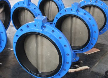
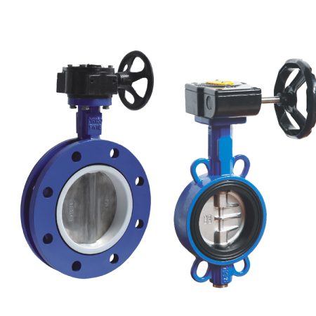
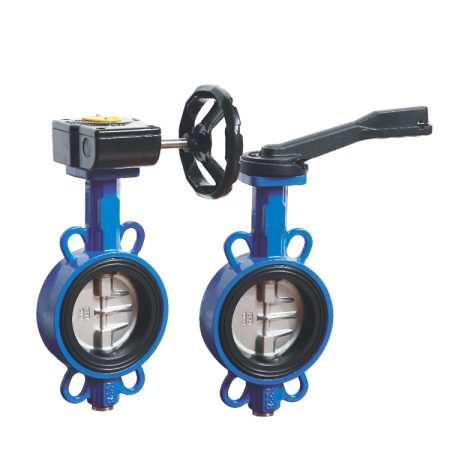
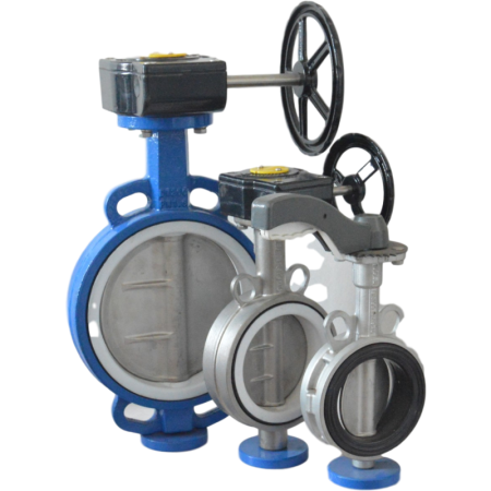
Lug Butterfly valve are a widely used type of flow control device, known for their simple design, compact size, and cost-effectiveness. They consist of a rotating disc mounted on a stem, which, when turned, either allows or restricts the flow of fluid through the valve. The disc’s position can be adjusted to achieve precise flow control, ranging from fully open to fully closed. Flanged Butterfly valve are commonly employed in various industries, such as water and wastewater treatment, oil and gas, chemical processing, power generation, and HVAC systems. Their applications include isolation, throttling, and flow regulation tasks, making them a versatile and reliable choice for managing fluid flow in a diverse array of settings. With their combination of efficiency, durability, and ease of operation, butterfly valves continue to play a crucial role in ensuring smooth and effective fluid flow management across numerous industrial sectors.
Importance of understanding valve symbols in engineering drawings and schematics
Comprehending valve symbols in engineering drawings and schematics is of paramount importance for professionals in the field, as these symbols serve as a universal language that facilitates effective communication and collaboration among team members. Accurate interpretation of valve symbols ensures that engineers, technicians, and other industry professionals can design, install, and maintain fluid flow control systems with precision and efficiency. Familiarity with these symbols allows for the seamless integration of components within complex piping networks while minimizing the risk of errors and miscommunications that could lead to costly downtime or safety hazards. Furthermore, understanding valve symbols contributes to better decision-making when selecting the most suitable valve type for a specific application, ultimately resulting in improved system performance and reliability. In essence, mastering the meaning of valve symbols in engineering drawings is crucial for maintaining high standards of safety, productivity, and operational excellence across various industries.
Butterfly Valve Basics
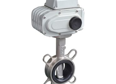
Butterfly valve symbol dwg are a fundamental component in fluid flow control systems, valued for their simplicity, compact design, and cost-effectiveness. At the heart of a butterfly valve lies a rotating disc mounted on a stem, which serves as the primary mechanism for regulating fluid flow. As the disc is turned, it pivots within the valve body, either permitting or obstructing the passage of fluid, depending on its position. The versatility of butterfly valves allows for precise control over fluid flow rates, with the disc’s position ranging from fully open to fully closed. This flexibility makes butterfly valves suitable for a variety of applications, including isolation, throttling, and flow regulation tasks. The valve’s components, such as the disc, stem, seat, and actuator, work in harmony to ensure smooth operation and dependable performance. Butterfly valves can be found across an array of industries, including water and wastewater treatment, oil and gas, chemical processing, power generation, and HVAC systems. Their widespread use can be attributed to their efficiency, durability, and ease of installation and maintenance, making them an indispensable tool for managing fluid flow in diverse industrial settings. As industry professionals continue to rely on butterfly valves for their flow control needs, understanding the basics of these versatile devices remains essential for achieving optimal system performance and longevity.
Description of butterfly valve components (disc, stem, seat, and actuator)
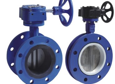
Butterfly valves consist of four main components that work together to regulate fluid flow effectively: the disc, stem, seat, and actuator. The disc, typically circular or slightly oblong in shape, is the central element responsible for controlling fluid passage. It rotates around the stem, a rod-like component that connects the disc to the actuator. The stem’s rotation allows the disc to pivot within the valve body, either opening or closing the flow path. The seat, usually made of resilient material, forms a tight seal against the disc when the valve is in the closed position, preventing fluid leakage. Lastly, the actuator is the driving force behind the valve’s operation, facilitating the rotation of the stem and disc. Actuators can be manual (operated by handwheel or lever), electric, pneumatic, or hydraulic, depending on the specific application requirements. Each component plays a crucial role in the overall function of the butterfly valve, contributing to its reliability and effectiveness in managing fluid flow across various industrial settings.
How butterfly valves operate (rotating disc to regulate flow)
Butterfly valves operate by utilizing a rotating disc to regulate fluid flow within a piping system. The disc, which is mounted on a stem, pivots within the valve body as the stem rotates, either permitting or obstructing the passage of fluid. When the disc is aligned parallel to the flow direction, it creates a wide-open path for fluid to pass through with minimal pressure loss, allowing for maximum flow. Conversely, when the disc is oriented perpendicular to the flow direction, it obstructs the fluid passage, effectively shutting off the flow. By adjusting the disc’s position between these two extremes, butterfly valves enable precise control over fluid flow rates, catering to various isolation, throttling, and flow regulation tasks. The simplicity and versatility of this rotating disc mechanism make butterfly valves an integral component in numerous industrial applications, ensuring efficient and reliable fluid flow management.
Common uses of butterfly valves in various industries
Butterfly valves are widely utilized across various industries due to their versatility, compact design, and cost-effectiveness in managing fluid flow. In the water and wastewater treatment sector, butterfly valves are employed to control the flow of water during filtration, disinfection, and distribution processes, ensuring efficient and safe operation. In the oil and gas industry, they are used for isolating and regulating the flow of crude oil, natural gas, and refined products in pipelines, storage tanks, and processing facilities. The chemical processing industry relies on butterfly valves to handle corrosive and abrasive fluids, maintaining precise control over the flow of chemicals during mixing, reaction, and transfer operations. Power generation plants utilize butterfly valves for managing the flow of steam, water, and other fluids in cooling systems, boilers, and turbines. Additionally, HVAC systems in commercial and residential buildings often incorporate butterfly valves for regulating the flow of chilled or heated water, contributing to energy-efficient climate control. These common uses across various industries highlight the indispensable role that butterfly valves play in ensuring effective and reliable fluid flow management.
The Butterfly Valve Symbol
In engineering drawings and schematics, the butterfly valve symbol serves as a visual representation of the valve, allowing for clear communication and understanding among professionals in various industries. The symbol typically consists of a circle bisected by a diagonal line, which represents the disc within the valve body. This diagonal line may be straight or slightly curved, depending on the specific type of butterfly valve being depicted. When the line is parallel to the flow direction, it indicates that the valve is in the open position, while a perpendicular orientation signifies a closed valve. Sometimes, an additional line perpendicular to the disc line is added to represent the valve stem.Understanding and interpreting the butterfly valve symbol is essential for engineers, technicians, and other industry professionals, as it enables them to design, install, and maintain fluid flow control systems with precision and efficiency. Familiarity with this symbol allows for seamless integration of butterfly valves within complex piping networks, contributing to improved system performance and reliability. Moreover, the ability to recognize and interpret the butterfly valve symbol in engineering drawings helps minimize the risk of errors and miscommunications that could lead to costly downtime or safety hazards.In summary, the butterfly valve symbol plays a crucial role in conveying vital information about the valve’s function and positioning within a fluid flow control system. This universally recognized symbol ensures effective communication among industry professionals and contributes to maintaining high standards of safety, productivity, and operational excellence across various sectors.
Explanation of the butterfly valve symbol in piping and instrumentation diagrams (P&ID)
In piping and instrumentation diagrams (P&ID), the butterfly valve symbol serves as a crucial visual element, enabling engineers, technicians, and other professionals to understand and interpret the valve’s function, position, and role within a fluid flow control system. The butterfly valve symbol is typically represented by a circle bisected by a diagonal line, which signifies the disc inside the valve body. This diagonal line can either be straight or slightly curved, depending on the specific type of butterfly valve being depicted. The orientation of the line indicates whether the valve is in an open or closed position – a parallel alignment to the flow direction represents an open valve, while a perpendicular orientation denotes a closed valve. In some cases, an additional perpendicular line may be included to represent the valve stem. Accurate interpretation of the butterfly valve symbol in P&ID drawings is essential for designing, installing, and maintaining efficient fluid flow systems, minimizing errors, and ensuring seamless integration of butterfly valves within complex piping networks. By providing a clear and concise representation of the butterfly valve’s function and status, the symbol contributes to effective communication among industry professionals and upholds high standards of safety and operational excellence across various sectors.
Key features of the symbol (circular disc with diagonal lines)
The key features of the butterfly valve symbol, commonly found in engineering drawings and schematics, are its simplicity and clarity, which allow for easy identification and understanding among industry professionals. The symbol primarily consists of a circular disc bisected by diagonal lines, representing the valve body and the internal disc, respectively. These diagonal lines can be straight or slightly curved, depending on the specific type of butterfly valve being depicted. The orientation of the lines provides essential information about the valve’s current position – when parallel to the flow direction, it signifies an open valve, while a perpendicular orientation indicates a closed valve. In some cases, an additional perpendicular line may be incorporated to represent the valve stem. The straightforward design of the butterfly valve symbol ensures that engineers, technicians, and other professionals can quickly and accurately interpret the valve’s function, status, and role within a fluid flow control system. This clear visual representation contributes to effective communication and coordination among team members, leading to improved safety, efficiency, and overall performance in various industrial applications.
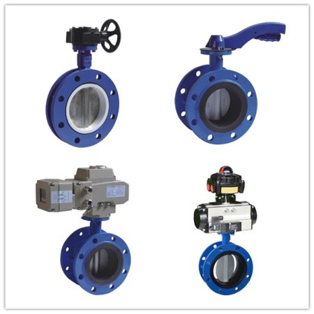
Variations of the symbol depending on actuation type (manual, electric, pneumatic, or hydraulic)
In engineering drawings and schematics, variations of the butterfly valve symbol are employed to indicate different actuation types, such as manual, electric, pneumatic, or hydraulic. These variations enable professionals to quickly identify the specific actuation mechanism used to control the valve’s position within a fluid flow system. For manual actuation, a small handwheel or lever symbol is often added adjacent to the valve, signifying that an operator adjusts the valve manually. In the case of electric actuation, a small box or motor symbol is typically placed next to the valve, denoting the presence of an electric motor powering the valve stem’s rotation. Pneumatic actuation, which uses compressed air to operate the valve, is represented by a symbol resembling a cylinder or diaphragm alongside the valve, indicating a pneumatic actuator. Lastly, hydraulic actuation, which relies on pressurized fluid for valve movement, incorporates a symbol similar to the pneumatic actuator, but with an added fluid reservoir or pump symbol to distinguish it from its pneumatic counterpart. By understanding these variations in the butterfly valve symbol, engineers, technicians, and other industry professionals can effectively communicate and coordinate their efforts, leading to improved safety, efficiency, and overall performance across various applications.
Reading and Interpreting Butterfly Valve Symbols
Reading and interpreting butterfly valve symbols in engineering drawings, schematics, and piping and instrumentation diagrams (P&ID) is a critical skill for engineers, technicians, and other industry professionals involved in designing, installing, and maintaining fluid flow control systems. These symbols provide essential information about the valve’s function, position, and actuation type, enabling effective communication and coordination among team members. The basic butterfly valve symbol consists of a circular disc bisected by diagonal lines, which represent the valve body and the internal disc, respectively. The orientation of the lines indicates the valve’s current position – parallel to the flow direction for an open valve and perpendicular for a closed valve.In addition to the basic symbol, variations exist to differentiate between actuation types, such as manual, electric, pneumatic, or hydraulic. Manual actuation is indicated by a small handwheel or lever symbol adjacent to the valve, while electric actuation is denoted by a small box or motor symbol. Pneumatic actuation, which uses compressed air to operate the valve, is represented by a cylinder or diaphragm symbol alongside the valve, whereas hydraulic actuation, which relies on pressurized fluid, incorporates a similar symbol with an added fluid reservoir or pump symbol.
Proficiency in reading and interpreting butterfly valve symbols ensures that industry professionals can accurately design, install, and maintain fluid flow systems, minimizing errors and miscommunications that could lead to costly downtime or safety hazards. This skill also allows for seamless integration of butterfly valves within complex piping networks, contributing to improved system performance, reliability, and operational efficiency. By fostering clear and concise communication through the use of universally recognized symbols, engineers, technicians, and other professionals can uphold high standards of safety, productivity, and operational excellence across various industries and applications.
Importance of accurate interpretation of valve symbols for system design and maintenance
The accurate interpretation of valve symbols, including butterfly valve symbols, is of paramount importance for system design and maintenance in various industrial applications. Engineers, technicians, and other industry professionals rely on these symbols to effectively communicate and understand the function, position, and actuation type of valves within a fluid flow control system. Accurate interpretation ensures that the right valves are selected and installed correctly, minimizing errors and miscommunications that could lead to costly downtime, safety hazards, or compromised system performance. Furthermore, precise understanding of valve symbols enables professionals to perform timely and efficient maintenance, ensuring the longevity and reliability of the fluid flow systems. In essence, the ability to accurately interpret valve symbols is crucial for maintaining high standards of safety, productivity, and operational excellence across diverse industries and applications.
Tips for reading and understanding valve symbols in engineering drawings
When reading and understanding valve symbols in engineering drawings, it is essential to follow a systematic approach to ensure accurate interpretation and avoid potential errors. Here are some tips for effectively deciphering valve symbols:
Familiarize yourself with the basic valve symbols and their variations, including butterfly valves, ball valves, gate valves, and others. Understand their unique features and design elements that distinguish them from one another.
Identify the orientation of the valve symbol, which indicates whether the valve is in an open or closed position. This information is crucial for understanding the current state of the fluid flow control system.
Look for additional elements or variations in the symbol that denote the actuation type – manual, electric, pneumatic, or hydraulic. Recognizing these variations will help you understand how the valve is controlled within the system.
Pay attention to any labels, tags, or annotations accompanying the valve symbols. These may provide critical information about the valve’s specifications, materials, or other essential details relevant to the system design and maintenance.
Cross-reference the valve symbols with equipment lists, schedules, or other documentation to obtain a comprehensive understanding of the system’s components and their interrelationships.
Collaborate with colleagues and consult relevant industry standards or guidelines to ensure a consistent and accurate interpretation of valve symbols across your team.
By following these tips, engineers, technicians, and other professionals can effectively read and understand valve symbols in engineering drawings, leading to improved system design, installation, and maintenance, as well as enhanced safety, efficiency, and overall performance.
Examples of butterfly valve symbols in different contexts (e.g., with fail-safe position, flow direction indication)
Butterfly valve symbols in engineering drawings and schematics can appear in various contexts, providing essential information about the valve’s function, actuation type, and additional features. For instance, a fail-safe position symbol may be included to indicate the valve’s default position (either open or closed) in case of power loss or system failure. This critical safety feature ensures that the valve will automatically return to its designated fail-safe position, preventing potential hazards or disruptions to the fluid flow system. Another example is the flow direction indication, which is typically represented by an arrow adjacent to the valve symbol. This arrow shows the intended direction of fluid flow through the valve, allowing engineers and technicians to properly design, install, and maintain the system. By including these context-specific elements in butterfly valve symbols, professionals can effectively communicate essential details about the valve’s operation and performance, ensuring accurate system design, seamless integration, and efficient maintenance across a wide range of industrial applications and fluid flow control systems.
Other Common Valve Symbols
In addition to butterfly valve symbols, there are several other common valve symbols used in engineering drawings and schematics to represent various types of valves and their functions within fluid flow control systems. These symbols help professionals communicate effectively and accurately design, install, and maintain such systems. Some of these common valve symbols include:
Ball Valve Symbol: Represented by a circle bisected by a straight line, the ball valve symbol indicates a valve with a spherical disc at its core that regulates fluid flow. The straight line represents the bore of the valve, which is either parallel or perpendicular to the flow direction when open or closed, respectively.
Gate Valve Symbol: Depicted as two triangular wedges facing each other, the gate valve symbol signifies a linear motion valve that controls fluid flow using a flat, vertical gate. The position of the gate (either fully open or closed) determines the flow state.
Globe Valve Symbol: This symbol consists of a circular disc with a curved line through it, representing the valve body and the internal movable disc or plug. Globe valves are commonly used for throttling applications, where precise control over fluid flow is required.
Check Valve Symbol: Illustrated as a single triangle or a triangle combined with a D-shaped loop, the check valve symbol denotes a valve designed to prevent backflow in a fluid flow system. Check valves automatically open or close depending on the fluid pressure and flow direction.
Diaphragm Valve Symbol: This symbol features a circular disc with a horizontal line and a curved line beneath it, symbolizing the valve body and the flexible diaphragm inside. Diaphragm valves are used to control fluid flow in systems requiring a high level of sanitation or corrosion resistance.
Plug Valve Symbol: Represented by a hexagonal shape intersected by a straight line, the plug valve symbol indicates a valve that employs a cylindrical or conical plug with a bored passage to control fluid flow. The plug’s rotation aligns the passage with the flow direction when open.
Needle Valve Symbol: This symbol comprises a circular disc intersected by an angled line, representing the valve body and the needle-like plunger inside. Needle valves are used for precise flow regulation in low-flow applications or high-pressure systems.
By understanding these common valve symbols, engineers, technicians, and other industry professionals can effectively communicate and coordinate their efforts, leading to improved system design, installation, and maintenance across various fluid flow control applications.
Brief overview of other valve types (ball valve, gate valve, globe valve, check valve) and their corresponding symbols
In fluid flow control systems, various valve types are employed for different purposes, each with its corresponding symbol in engineering drawings and schematics. Ball valves, represented by a circle bisected by a straight line, use a spherical disc with a bore to regulate fluid flow. The straight line indicates the valve’s open or closed position, depending on its alignment with the flow direction. Gate valves, depicted as two triangular wedges facing each other, utilize a flat, vertical gate that moves linearly to control fluid flow. Globe valves, illustrated by a circular disc with a curved line through it, employ an internal movable disc or plug for precise throttling applications. Lastly, check valves, denoted by a single triangle or a triangle combined with a D-shaped loop, are designed to prevent backflow in fluid flow systems by automatically opening or closing based on fluid pressure and flow direction. Familiarity with these valve types and their corresponding symbols is crucial for engineers, technicians, and other industry professionals to effectively design, install, and maintain fluid flow control systems.
Comparison of butterfly valve symbols with other valve symbols
Butterfly valve symbols, like other valve symbols, play a vital role in conveying essential information about the valve’s function and position within fluid flow control systems. A butterfly valve symbol typically consists of a circle with a short straight line or a curved line bisecting it, representing the valve body and the disc inside. In contrast, other valve symbols have distinct features that differentiate them from butterfly valve symbols and each other. For example, ball valve symbols feature a circle bisected by a longer straight line, indicating the spherical disc with a bore; gate valve symbols display two triangular wedges facing each other, signifying the flat, vertical gate; globe valve symbols comprise a circular disc with a curved line through it, denoting the internal movable disc or plug; and check valve symbols use a single triangle or a triangle combined with a D-shaped loop, representing the valve’s backflow prevention mechanism. Recognizing and understanding these differences among butterfly valve symbols and other valve symbols is crucial for engineers, technicians, and other industry professionals to accurately design, install, and maintain fluid flow control systems across various applications.
Conclusion
In conclusion, understanding valve symbols, including wafer butterfly valve symbols and other common valve symbols, is essential for professionals working with fluid flow control systems. Accurate interpretation of these symbols in engineering drawings and schematics ensures proper design, installation, and maintenance of these systems, ultimately leading to enhanced safety, efficiency, and overall performance. Familiarity with various valve types, their functions, and their corresponding symbols allows engineers, technicians, and other industry professionals to communicate effectively and coordinate their efforts across a wide range of applications. By adopting a methodical approach to deciphering valve symbols and staying up-to-date with relevant industry standards and guidelines, professionals can contribute to the continued advancement and innovation within the fluid flow control domain.
Recap of the significance of the butterfly valve symbol in engineering drawings
To recap, the butterfly valve symbol holds significant importance in engineering drawings, as it effectively communicates crucial information about the valve’s function, position, and additional features within fluid flow control systems. This symbol, typically represented by a circle with a short straight line or a curved line bisecting it, allows engineers, technicians, and other industry professionals to accurately design, install, and maintain systems that incorporate butterfly valves. By understanding the nuances of the butterfly valve symbol and its variations (e.g., fail-safe position, flow direction indication), professionals can ensure proper integration and operation of butterfly valves across various applications. In essence, the butterfly valve symbol serves as a vital tool for conveying essential details about the valve’s role in fluid flow control systems, contributing to improved system performance, safety, and efficiency.
Importance of familiarizing oneself with valve symbols for effective communication and collaboration in the industry
Familiarizing oneself with valve symbols, including butterfly valve symbols and other common valve symbols, is of paramount importance for effective communication and collaboration within the fluid flow control industry. As these symbols convey essential information about valve types, functions, and positions within a system, understanding them enables engineers, technicians, and other industry professionals to accurately design, install, and maintain fluid flow control systems across various applications. Moreover, being well-versed in valve symbols ensures that professionals can seamlessly collaborate with their peers, preventing potential misunderstandings, errors, or miscommunications. In turn, this leads to increased safety, efficiency, and overall performance of fluid flow control systems. By prioritizing the acquisition of knowledge related to valve symbols, professionals in the industry can contribute to a smoother exchange of ideas and expertise, fostering innovation and advancement in the field of fluid flow control.


-150x150.jpg "Unveiling the Significance of butterfly valve Philippines Oil and Gas Industry")