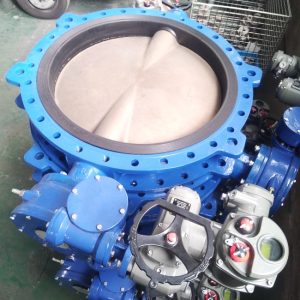
Are you in search of a reliable, durable and high-quality pneumatic butterfly valve for your industrial applications? Look no further! The Fluorine Lined Butterfly Valve is here to save the day. With its unique PTFE lining material and top-notch construction, this valve is designed to excel in all sorts of demanding conditions.
What Sets the PFA Lined Butterfly Valve Apart?
The secret behind the incredible performance of our ptfe lined butterfly valve lies in its PTFE (Polytetrafluoroethylene) lined seat and valve plate. This advanced material combines the best of both worlds—mechanical strength and unbeatable chemical resistance. A valve that can withstand harsh mediums like acids, alkalis, salts, oxidants, reductants, and organic solvents, making it an ideal choice for industries like chemical, petroleum, medicine, food, steel melting, papermaking, and water and electricity systems.
Key Benefits:
Excellent anticorrosion performance
Wide compatibility with various industrial applications
Long-lasting and durable
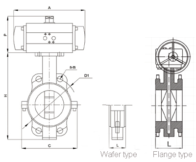
A Closer Look at the PTFE Lined Butterfly Valve Specifications
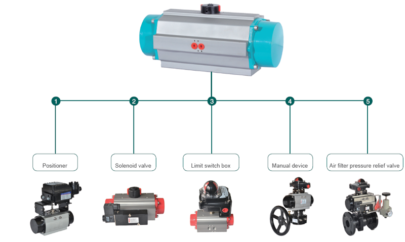
Optional Accessories: Solenoid valve, limit switch box, air filter relief pressure valve, E/P positioned, and manual device.
So why wait? Upgrade to the superior Fluorine Lined Butterfly Valve and experience the difference for yourself! Confidently tackle even the most challenging industrial applications while enjoying peace of mind that comes with a top-quality product.
Order your Fluorine Lined Butterfly Valve today and give your business the boost it deserves!
Technical parameters
Body
GGG40
Disc/shaft one piece
CF8M
1.4462
CF8M FEP lined
CF8 EPDM lined
Seat
PTFE,FPM,EPDM,PU,NBR
PTFE
EPDM
Body style
wafer
Nominal diameter
2″ – 40″ (DN50mm – DN1000mm)
Top flange
ISO5211
Operating pressure
16bar for DN50-DN200, 10bar for DN250-DN1000
Temperature range
-20 °C to + 180 °C (depending on pressure, medium and material)
Body style
Wafer,LUG,Flange
Flange accommodation
EN 1092 PN 6/PN10/PN16
ASME Class 150
AS 4087 PN10/ PN16
JIS 5K/10K
A PTFE (Polytetrafluoroethylene) Lined Butterfly Valve is a robust and innovative solution within the valve manufacturing industry, specifically designed to manage corrosive and harsh fluid flow in various pipeline systems.
The defining feature of this valve is its PTFE lining, a high-performance fluoropolymer known for its exceptional chemical resistance, low friction coefficient, and excellent temperature endurance. This lining forms a protective barrier between the valve’s metal components and the passing fluid, effectively shielding the valve from potential corrosion or damage due to aggressive media.
At the heart of this valve lies a disc-shaped closure mechanism, which rotates around a central axis to control the fluid passage. The disc’s operation is facilitated by either a manual lever or an automated actuator, ensuring precision control over the valve’s open and close process.
The difference between PTFE lined butterfly valve and rubber lined butterfly valve?
A PTFE Lined Butterfly Valve and a Rubber Lined Butterfly Valve are both pivotal assets in the valve manufacturing industry, each specifically engineered to control fluid flow within various pipeline systems. However, the primary distinction between these two lies in their respective lining materials and the applications they are best suited for.
A PTFE (Polytetrafluoroethylene) Lined Butterfly Valve is characterized by its high-performance fluoropolymer lining, known for its exceptional chemical resistance, low friction coefficient, and excellent temperature endurance. This lining forms an effective shield between the valve’s metal components and the flowing media, offering superior protection against potential corrosion or damage from aggressive substances. The PTFE Lined Butterfly Valve is ideal for applications involving corrosive chemicals, acids, and other harsh substances, where its durability and operational efficiency shine.
Contrastingly, a Rubber Lined Butterfly Valve features a resilient rubber lining, renowned for its flexibility and wear resistance. This lining provides a tight seal and dampens vibration, making it particularly suitable for handling abrasive slurries, water, air, and other non-corrosive media. The rubber lining also contributes to a reduced torque requirement, enabling easier operation and potentially extending the valve’s service life.
What media conditions are PTFE lined butterfly valves used for?
PTFE Lined Butterfly Valves, the paragons of robustness and efficiency in our valve portfolio, are meticulously engineered for controlling fluid flow under challenging media conditions. Their defining feature, the PTFE (Polytetrafluoroethylene) lining, is a high-performance fluoropolymer celebrated for its exceptional chemical resistance, low friction coefficient, and superior temperature endurance.
These valves are specifically designed to tackle aggressive and corrosive media conditions. The PTFE lining forms a protective barrier between the valve’s metal components and the passing fluid, effectively safeguarding the valve against potential corrosion or damage. This makes them ideal for applications involving a wide range of corrosive chemicals, including strong acids, alkalis, solvents, and other harsh substances.
Moreover, with their excellent temperature resilience, PTFE Lined Butterfly Valves can comfortably handle media with elevated temperatures, further expanding their application scope. Their durability and operational efficiency make them an indispensable asset in industries such as chemical processing, petrochemical, pharmaceutical, power generation, and water treatment, among others.
In summary, PTFE Lined Butterfly Valves are the optimal choice for managing fluid flow under adverse media conditions, especially when dealing with corrosive substances and high temperatures. As an industry leader in valve manufacturing, we confidently offer these high-performance valves, reinforcing our commitment to quality, innovation, and technical excellence.
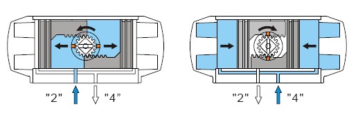
Pneumatic actuator working principle:
Double acting
(Counterclockwise)
Compressed air to Port 2 forces the pistons outwards, causing the output shaft to turn counterclockwise, while the air is being exhausted from Port 4.(Clockwise) Air to Port 4 forces the pistons inwards, causing the pinion to turn clockwise while the air is being exhausted from Port 2.
Single acting
(Clockwise)
Loss of air pressure, the stored energy in the springs forces the pistons inwards,the pinion turns clockwise, while air is being exhausted from Port 4.


")
")


 (Counterclockwise)
Compressed air to Port 2 forces the pistons outwards, causing the output shaft to turn counterclockwise, while the air is being exhausted from Port 4.(Clockwise) Air to Port 4 forces the pistons inwards, causing the pinion to turn clockwise while the air is being exhausted from Port 2.
Single acting
(Counterclockwise)
Compressed air to Port 2 forces the pistons outwards, causing the output shaft to turn counterclockwise, while the air is being exhausted from Port 4.(Clockwise) Air to Port 4 forces the pistons inwards, causing the pinion to turn clockwise while the air is being exhausted from Port 2.
Single acting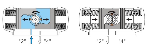 (Clockwise)
Loss of air pressure, the stored energy in the springs forces the pistons inwards,the pinion turns clockwise, while air is being exhausted from Port 4.
(Clockwise)
Loss of air pressure, the stored energy in the springs forces the pistons inwards,the pinion turns clockwise, while air is being exhausted from Port 4.