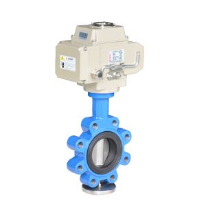
The Electric Triple Offset Butterfly Valve is a highly reliable and efficient solution for process flow control in a variety of industries. This advanced double offset butterfly valve technology features a zero-leakage design, ensuring optimal performance and minimal maintenance requirements. With its robust construction and intrinsic fire safety, this valve is an exceptional choice for applications in Oil & Gas, Chemical & Coal, Petrochemical, Desalination Plants, Waterworks, Fossils, District Heating, Nuclear, Iron & Steel, Mining, Automotive, Shipyards, and Aerospace industries.
Key Features
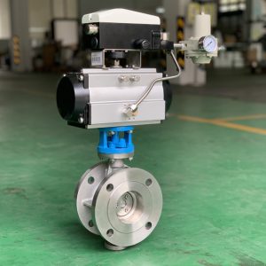
ISO 5211 Mounting Bracket: Enables easy mounting of actuators for safe and efficient valve operation.
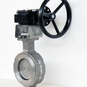
Triple Offset Design: Offers superior sealing performance and prolonged service life through its ellipsoidal sealing geometry.
Zero Leakage: Provides a bubble-tight shut-off, ensuring that there is no rubbing during 90-degree rotation across various pressure and temperature conditions.
Inherently Firesafe: Designed to prevent fire hazards, further enhancing the safety and reliability of the valve.
Durable Construction: Features a metal seal ring made from Duplex material and a highly wear-resistant Stellite grade 21 seat, ensuring prolonged superior tightness.
Interchangeable Design: The single-piece cast body complies with ISO 5752, ASME B16.10, and API 609 double-flanged short pattern standards, guaranteeing easy interchangeability with other valve types.
Applications
The Electric Triple Offset Butterfly Valves is widely utilized in numerous industries for its exceptional performance, flexibility, and durability. Some common applications and industries include:
Oil & Gas: Provides reliable flow control and leak prevention in refineries and transmission pipelines.
Chemical & Coal: Delivers safe, precise, and leak-free operation in chemical processing plants and coal mining operations.
Petrochemical: Offers a high level of operational efficiency and reliability in petrochemical processes.
Desalination Plants: Ensures optimal water flow control and minimal leakage in water
FEATURES
ISO 5211 bracket for easy mounting of actuators
Triple offset and ellipsoidal sealing geometry
Bubble tight shut-off
Inherently firesafe by design
A metal seal ring in Duplex and a highly wear-resistant Stellite grade 21 seat ensure prolonged superior tightness
Single piece cast body with face to face dimensions to ISO5752, ASME B16.10 and API 609 double flanged short pattern, guarantees interchangeability with other valve types
Extensively hardened bearings, incorporating a standard reinforce, braided, flexible graphite bearing protector, ensure increased reliability
Blowout proof devices on shaft keep sure safety of shaft operating
Pin-less shaft to disc connection makes the valve convenient for parts replacement and reliable even under corrosion
Connection
Double flange
Size
3″-80″ for PN10,PN16,Class150; 3″-48″ for PN25,PN40,Class300; 3″-24″ for Class600
On-off type: feedback signal: Passive contact signal/4-20mA/ resistance signals.
Regulation type: Input signal 4-20mA/0-10V/1-5V;
Feedback signal: 4-20mA/0-10V/1-5V
Voltage: AC220V380V110V24V、DC12V24V etc;Special voltage can be customized.
Explosion-proof class: Can be choose explosion-proof type EX d IIBT4
Type
Control type
Function
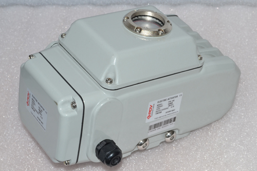
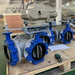
Electric actuator
ON-OFF type
Feedback: the active signal, passive contact signal, resistance, 4-20mA
Regulation type
Input and output signal: 4-20mA, 0-10v, 1-5v, switch, MODBUS, PROFIBUS field bus
Filed operation
The field, remote control switch regulation and MODBUS, PROFIBUS field bus
FAQS
What is an triple offset butterfly valve?
The double eccentric offset butterfly valve can also be called the high-performance butterfly valve or double eccentric butterfly valve. This valve is suitable for thicker media that has a high pressure because its design does not allow too much contact with the disc and seat.
Double Offset Butterfly Advantages
The balance of this valve is in the stem placed behind the circular disc. It allows the disc to self-adjust to the center, ensuring tight sealing. Even when the valve is fully opened, the valve does not touch the soft seat, ensuring a longer service life.
What is a butterfly valve used for?
Uses for butterfly valves include regulating the volumes/flows entering into pipe systems during start up operations; isolating areas within larger piping networks; aiding in preventing backflow; serving as check-valves when unexpected flow reversals occur; providing throttling action for modulating fluid flows rates into certain sections of piping systems (similarly applicable to hydraulic pumps); draining fluid out of units where gravity assisted drainage occurs; providing a shutoff option prior to maintenance work being carried out on system components downstream from the unit containing the butterfly valve itself.
In addition to their various uses listed above, one primary advantage that butterfly valves offer over other types of isolation or control valves is their extremely compact size relative to how much performance they deliver
Caustic,
Corrosive,
Dry Chlorine,
Oxygen,
Seawater,
Sour Gas,
Steam,
Toxic
Ultra Pure Water,
Vacuum, and
Industries
Chemical,
Food and Beverage,
HVAC,
Mining,
Oil and Gas,
Petrochemical,
Pharmaceutical,
Power Generation,
Pulp and Paper,
Refining,
Sugar Processing, and
Water Filtration.
How do I choose a triple offset butterfly valve?
Choosing a triple offset butterfly valve can seem daunting at first, but with the right knowledge and information, it’s an easy task. To find the right double eccentric butterfly valve for your application, you should consider several factors:
Flow Characteristics – triple offset butterfly valve are designed to control flow rates from low to high levels. Since this type of valve has two seats instead of one, they offer better performance when controlling higher flow rates compared to other types of valves. When selecting a Double Eccentric Butterfly Valve, you’ll need to determine the appropriate size for your intended use and check that it meets any applicable standards (such as ASME or API).
Installation Requirements – Taking into account where and how you plan on installing your Double Eccentric Butterfly Valve is important in making sure that installation is successful and efficient. If your installation site has limited space constraints then choosing a smaller model may be necessary – while also ensuring that its port configuration matches up with existing piping systems connected downstream or upstream from it will make things easier come time for installation
Pressure Rating – The pressure rating provided by your chosen Double Eccentric Butterfly Valve should match up with the requirements needed for operation within its respective application/environment . Pressure ratings typically given in psi (Pounds per Square Inch) or bar(s), so be sure to familiarize yourself beforehand with what data points are included within those units before starting out on this part of selection process!
Materials – Selecting the correct material is critical when selecting any type of valve due its direct impact on system life cycle costs as well as safety considerations; materials used can range from steel alloys such stainless 304L & CF8M depending on chemical compatibility / corrosion resistance requirements associated with particular system fluid being switched through them . Carefully consider these!
Actuation Options– Whether manual operation (lever operated) or automated via actuation , having access to multiple sources available will let users choose whichever option best fits their needs; manual levers provide cost-effectiveness while electric actuators add convenience but can rack up additional costs over time due maintenance etc…
What are valve electric actuators?
Valve electric actuators are devices commonly used in industrial automation to open, close, and control the flow of fluids such as water, fuel, steam or air. They are designed to be compact yet powerful and offer a reliable solution for accurate positioning and precise control of valves.
The basic operation of an electric actuator involves supplying electrical energy which moves an output motor that controls the movement of a stem or valve disc attached to the output shaft. When this stem or valve disc is rotated against a valve seating surface it opens or closes the valve allowing fluid to pass through its ports. It may also be equipped with feedback sensors that provide positional information from both the positioner and/or limit switches located on the electric actuator’s body enabling more accurate positioning accuracy when controlling processes with changing pressures or temperatures.
Butterfly valve PN16 Flange size chart
NPS
DN
OD
PCB
Bolt
n-bolt
3/8
DN10
90
60
14
4
1/2
DN15
95
65
14
4
3/4
DN20
105
75
14
4
1
DN25
115
85
14
4
11/4
DN32
140
100
18
4
11/2
DN40
150
110
18
4
2
DN50
165
125
18
4
21/2
DN65
185
145
18
8
3
DN80
200
160
18
8
4
DN100
220
180
18
8
5
DN125
250
210
18
8
6
DN150
285
240
22
8
8
DN200
340
295
22
12
10
DN250
405
355
26
12
12
DN300
460
410
26
12
14
DN350
520
470
26
16
16
DN400
580
525
30
16
18
DN450
640
585
30
20
20
DN500
715
650
33
20
24
DN600
840
770
36
20
28
DN700
910
840
36
24
32
DN800
1025
950
39
24
36
DN900
1125
1050
39
28
40
DN1000
1255
1170
42
28
48
DN1200
1485
1390
48
32
56
DN1400
1685
1590
48
36
64
DN1600
1930
1820
56
40
72
DN1800
2130
2020
56
44
80
DN2000
2345
2230
62
48
Butterfly valve ASME ANSI CLASS 150LB Flange size chart
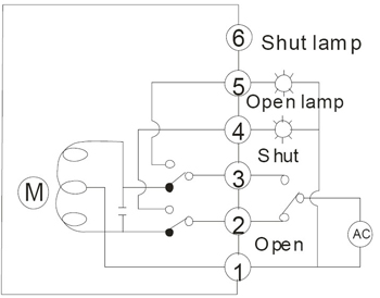
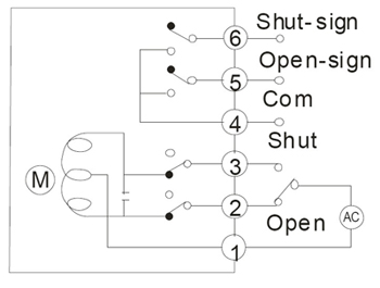
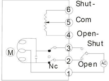
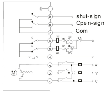
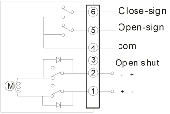
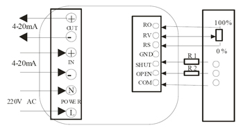
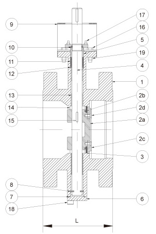
Electric butterfly valve wire drawing
Complete with POE sereis electric actuator
On-off type with light indicator signal feedbackOn-off type with light indicator signal feedbackOn-off type with passive contact signal feedbackOn-off type with resistance potentiometer feedbace wiring diagramAC380V three-phase power supply wiring diagram with passive signal feedbackDC24V DC12V direct on-off type wiring diagramIntelligent regulation type electric actuator wiring diagram AC220V AC380V DC24C the wire drawing are the same.
")


-150x150.jpg "A Comparison of Concentric, Double-Offset, and Triple-Offset Butterfly Valve in the USA")